Method and system for facilitating no-break power transfer

a technology of power transfer and no-break power, applied in the direction of emergency power supply arrangement, machines/engines, magnetic bodies, etc., can solve the problems of no-break power transfer, apu overload, high-temperature problems in the apu,

Inactive Publication Date: 2008-08-26
HAMILTON SUNDSTRAND CORP
View PDF42 Cites 20 Cited by
  • Summary
  • Abstract
  • Description
  • Claims
  • Application Information

AI Technical Summary

Benefits of technology

[0007]The present invention is directed to an improved method and system for facilitating no-break power transfer between an APU and a main engine. In one embodiment, the APU controller receives information from the aircraft computer regarding the main engine's speed and calculates a target APU speed for no-break power transfer. The APU controller then adjusts the APU speed up or down to the target APU speed. The rate at which the APU speed is adjusted may be controlled so that it ramps the APU speed to the required APU speed as quickly as possible while optimizing fuel consumption during the ramping.
[0008]The APU controller may also determine a maximum electrical load that the APU can sustain using various APU operating parameters. This threshold information is provided to an aircraft computer, and the aircraft computer adjusts an aircraft electrical load until it falls below the threshold, thereby avoiding overloading the APU during the power transfer.

Problems solved by technology

No-break power transfer poses its own problems, however.
First, the APU may be required to carry a large electrical load during the frequency matching process, potentially causing the APU to overload and cause high-temperature problems in the APU.
Electrical overload is particularly a problem if the APU is loaded solely by an electrical load with no pneumatic load that can be reduced to compensate for the increased electrical load.
This makes successful frequency matching between the APU and the main engine more difficult because the APU and the engine no longer return to a single predetermined fixed speed; instead, the speed can vary over a wide range.

Method used


Image

  • Method and system for facilitating no-break power transfer
  • Method and system for facilitating no-break power transfer
  • Method and system for facilitating no-break power transfer

Examples


Embodiment Construction

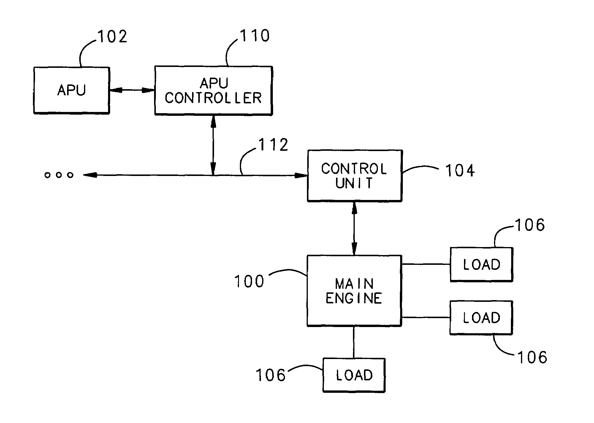
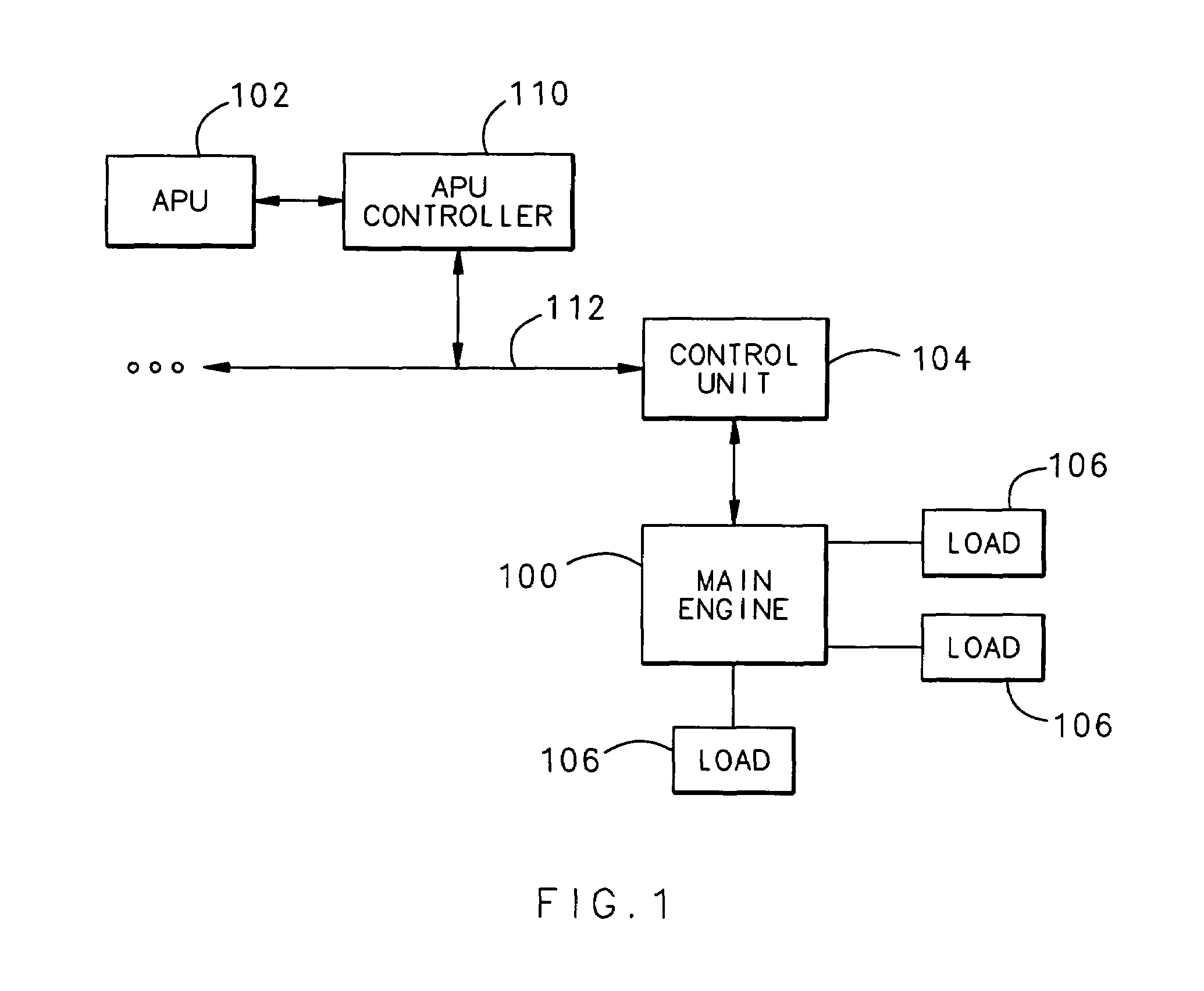
[0013]FIG. 1 is a block diagram illustrating an operating environment of the present invention. The invention is generally directed to a system that allows no-break power transfer between a main engine 100 and an APU 102. The main engine 100 can be an aircraft engine generator, ground power connected to an airport terminal, or any other similar device. Although the example below focuses on an aircraft engine acting as the main engine 100, those of ordinary skill in the art will understand that the invention is applicable to any system where no-break power transfer between a main engine 100 and an APU 102 is desired.

[0014]The main engine 100 is controlled by a control unit 104, such as a generator control unit or aircraft computer, and provides power to electrical devices, or loads 106. The loads 106 can be any device that draws power from the engine 100. In the case of an aircraft, for example, the loads 106 may be aircraft devices such as galleys, passenger compartment devices, coc...


PUM


Abstract

An improved method and system for facilitating no-break power transfer between an APU and a main engine includes determining a required APU speed for conducting power transfer based on various APU operating parameters, such as engine speed, fuel, environmental temperature, etc. The APU controller then adjusts the APU speed up or down to the required APU speed. Communication between an aircraft computer and the APU controller may also be provided so that operational data can be exchanged to adjust the electrical load of the aircraft below a maximum load threshold set by the APU, avoiding overloading of the APU during power transfer. By exchanging operational data between the APU controller and the aircraft computer, both the APU and the electrical load can be adjusted to optimize no-break power transfer despite varying APU operating conditions and main engine generator frequencies.

Description

TECHNICAL FIELD[0001]The present invention relates to aircraft engine controls, and more particularly to a method and system for transferring power between a main aircraft engine and an auxiliary power unit.BACKGROUND OF THE INVENTION[0002]Auxiliary power units (APUs) are gas turbine engines used in aircraft systems to provide pneumatic and electrical power to the aircraft, primarily when the aircraft is on the ground. This pneumatic and electrical power is provided by the main propulsion engines when the aircraft is in flight. Power transfers are required between the APU and the main engines at the beginning and at the end of aircraft flights. Additionally, electrical power transfers are also required between the APU and ground power supplies.[0003]Current aircraft designs typically operate electrical power systems at a constant frequency. Electrical power transfers for this type of system can either be a “break transfer,” during which neither the APU nor the main engine generator ...

Claims


Application Information

Patent Timeline
Patent Type & Authority Patents(United States)
IPC IPC(8): H02J3/08H02J3/42
CPCF02C9/00F02C9/42F05D2220/50
Inventor SUTTIE, PETER J.
Owner HAMILTON SUNDSTRAND CORP
Why Eureka
Try Eureka