Internal voltage generator

a technology of internal voltage and generator, which is applied in the direction of electric variable regulation, process and machine control, instruments, etc., can solve the problem of standby current increasing to a level that exceeds the desired specification, and achieve the effect of dissipating a large amount of curren

Active Publication Date: 2008-08-26
SK HYNIX INC
View PDF14 Cites 30 Cited by
  • Summary
  • Abstract
  • Description
  • Claims
  • Application Information

AI Technical Summary

Problems solved by technology

However, the increase in the number of the internal voltage generators may cause standby current to increase to a level that exceeds the desired specification of the semiconductor memory device.

Method used


Image

  • Internal voltage generator
  • Internal voltage generator
  • Internal voltage generator

Examples


first embodiment

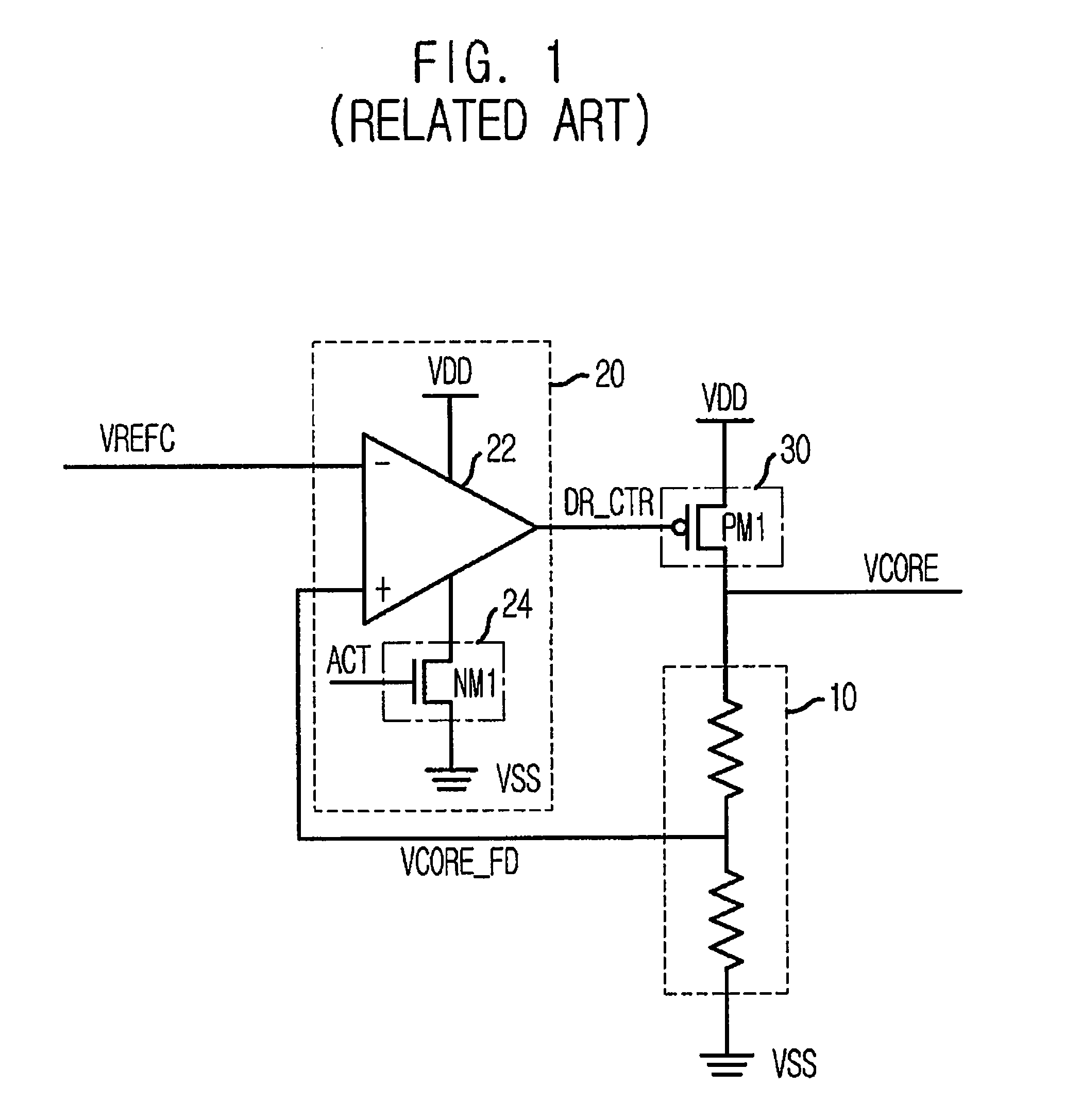
[0014]FIG. 1 is a circuit diagram showing an internal voltage generator in accordance with the present invention.

[0015]Referring to FIG. 1, the internal voltage generator includes an internal voltage driver 30 for supplying an internal voltage VCORE, a feedback circuit 10 for supplying a feedback voltage VCORE_FD having a voltage level proportional to the internal voltage VCORE, and a control signal generating circuit 20 for generating a control signal DR_CTR to control the internal voltage driver 30 such that the feedback voltage VCORE_FD is maintained at a desired reference voltage VREFC.

[0016]The feedback circuit 10 includes a plurality of resistors connected in series between the interval voltage VCORE and a ground voltage VSS.

[0017]The control signal generating circuit 20 includes a differential amplifier 22 receiving the reference voltage VREFC and the feedback voltage VCORE_FD, and a driving controller 24 having an NMOS transistor NM1 for supplying a driving voltage to the di...

second embodiment

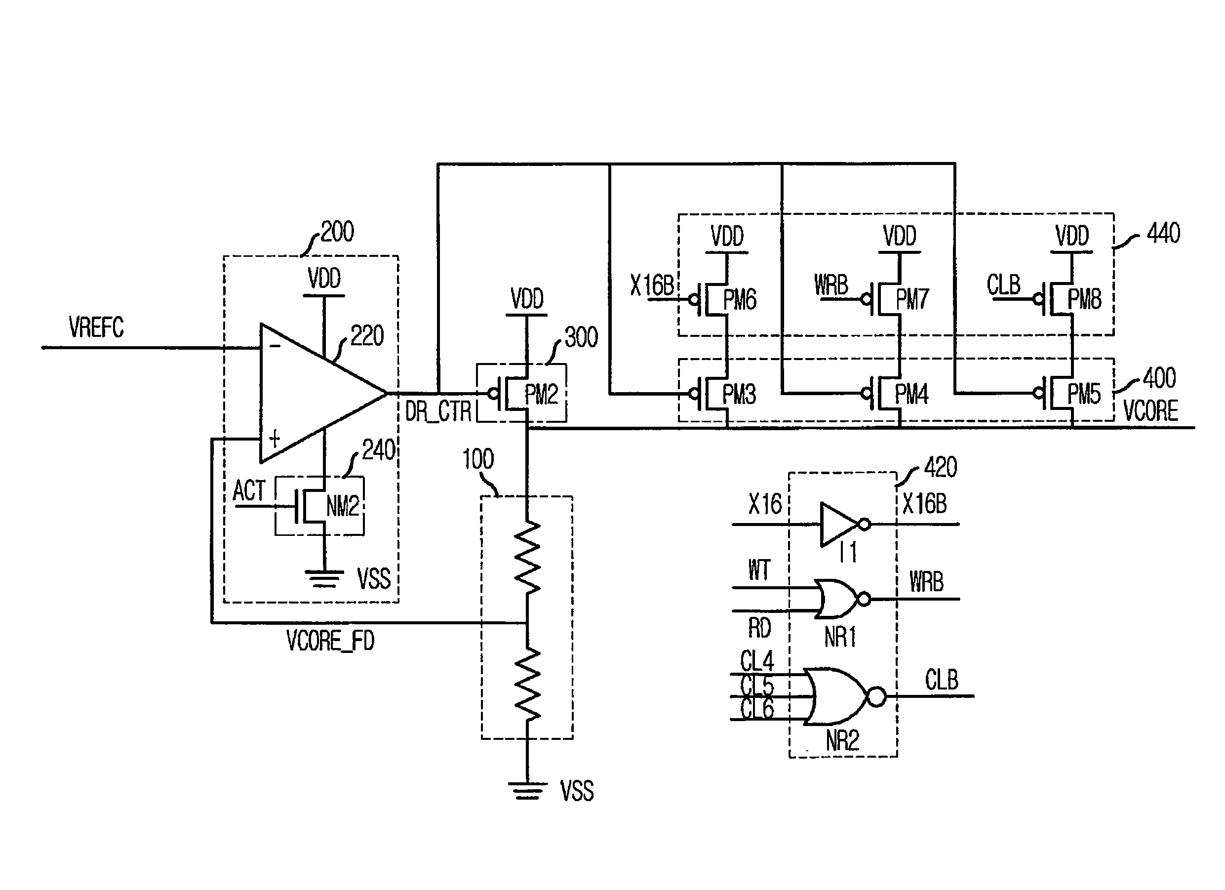
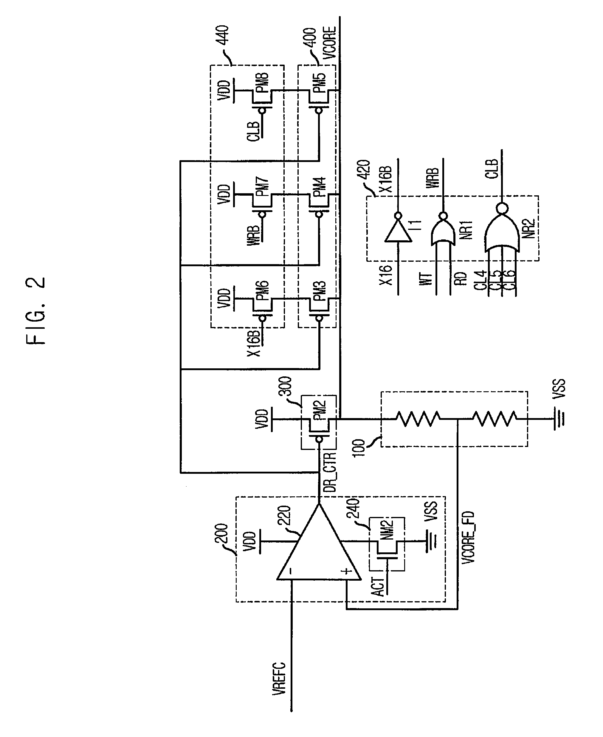
[0021]FIG. 2 is a circuit diagram showing an internal voltage generator in accordance with the present invention.

[0022]Referring to FIG. 2, the internal voltage generator includes an internal voltage driver 300 for supplying an internal voltage VCORE, a feedback circuit 100 for supplying a feedback voltage VCORE_FD having a voltage level proportional to the internal voltage VCORE, a control signal generating circuit 200 for generating a control signal DR_CTR to control the internal voltage driver 300 such that the feedback voltage VCORE_FD is maintained at a desired reference voltage VREFC, and an auxiliary driving circuit 400 for additionally supplying the internal voltage VCORE in response to the control signal DR_CTR.

[0023]The feedback circuit 100 includes a plurality of resistors connected in series between the interval voltage VCORE and a ground voltage VSS.

[0024]The control signal generating circuit 200 includes a differential amplifier 220 receiving the reference voltage VREF...


PUM


Abstract

An internal voltage generator supplies a stable internal voltage without increasing standby current. The internal voltage generator includes an internal voltage driver for supplying an internal voltage based on a control signal, a feedback circuit for supplying a feedback voltage having a voltage level proportional to the internal voltage, a control signal generating circuit for generating the control signal to control the internal voltage driver such that the feedback voltage is maintained at a desired reference voltage, an auxiliary driving circuit for additionally supplying the internal voltage in response to the control signal, and an auxiliary driving control circuit for activating the auxiliary driving circuit only when it is expected to dissipate a large amount of a current.

Description

FIELD OF THE INVENTION[0001]The present invention relates to a semiconductor device; and, more particularly, to an internal voltage generator for supplying a stable internal voltage without increasing a standby current.DESCRIPTION OF RELATED ARTS[0002]In a semiconductor memory device, an internal voltage generator receives an external voltage VDD to generate an internal voltage having various levels.[0003]With the recent trend of low voltage and low power consumption, an internal voltage generator is employed in a dynamic random access memory (DRAM).[0004]Since the internal voltage of the semiconductor memory device is generated therewithin, many attempts have been made to generate a stable internal voltage without regard to changes of ambient temperature, process, pressure, etc.[0005]Often, a plurality of internal voltage generators are provided to supply an amount of current required by the semiconductor memory device. In a DDR2 memory device, which output 16-bit data instead of 4...

Claims


Application Information

Patent Timeline
Patent Type & Authority Patents(United States)
IPC IPC(8): G05F1/10
CPCG11C5/147G05F1/465
Inventor CHOI, JUN-GISHIN, YOON-JAE
Owner SK HYNIX INC
Why Eureka
Try Eureka