Method and apparatus for performing an ultrasonic survey

a technology of ultrasonic and surveying equipment, applied in direction finders using ultrasonic/sonic/infrasonic waves, vessel construction, instruments, etc., can solve the problems of time-consuming process, position measurements subject to errors, and expensive process, so as to reduce the cost of hull survey and the time necessary

Inactive Publication Date: 2008-08-26
SONICWORKS
View PDF4 Cites 6 Cited by
  • Summary
  • Abstract
  • Description
  • Claims
  • Application Information

AI Technical Summary

Benefits of technology

[0017]It can be shown that with motion compensation, wasting and other measurements of the hull made from an accurately locatable robot flying around the hull can result in a virtually continuous mapping of hull defects. This is because accurate measurements can be done on one-centimeter centers. As a result, all hull defects will be detected with no gaps.
[0036]Moreover, the time necessary for completing such a survey is not on the order of weeks but on the order of hours, with the number of personnel reduced from five-to-ten divers to the use of one diver and a maneuverable robot, thus cutting the cost of the hull survey by a factor of five and cutting the time necessary for keeping the vessel out of service for the survey by tenfold.

Problems solved by technology

The most common way to obtain the governmental certificate is to dry-dock the vessel, an expensive process, and to both visually and ultrasonically inspect the hull of the vessel when it is in dry dock.
The accuracy of the measured point on the hull is a function of how accurate the manual surveying is, which is a time-consuming process.
One generally has to measure the distance of the head of the surveying instrument to the fiducial point utilizing mechanical gauges, measuring rods or bars and the like, with position measurements being subject to error.
As a result of the difficulty of accurately specifying the location of the surveying instrument, surveyors typically measure out a one-foot grid across the surface of the hull and take measurements at the cross-points.
The problem, however, is that with one-foot spacing, wasting and other defects in the hull are oftentimes missed if they occur between the cross-points.
The location of the diver making the survey and thus the points surveyed is likewise problematic, with physical measurements of a surveyed point underwater being much more difficult than when the ship is hauled out.
However, positional inaccuracies are in the one-meter range.
Thus, whether there is an in-water survey through the utilization of divers or whether the vessel is hauled out for the survey, in the past, surveys have suffered from the fact that the number of actual measurements made on the hull is limited, meaning that there are areas of the hull which remain unsurveyed.
Wasting, sometimes underneath support structures within the hull and at places where they are not visible, contribute to the unseaworthiness of the vessel.
Historically, vessels within weeks of having been surveyed have broken up at sea due to the fact that wasting and other defects were not uncovered by the survey.
However, it is impossible to render the ship motionless against winds, tides and current, even if anchored bow and stern.
There is always a certain amount of motion of the vessel due to currents and wave action so that depending on the size of the vessel, the hull may move by many meters, which directly impacts trying to ascertain where the survey measurements were made.

Method used


Image

  • Method and apparatus for performing an ultrasonic survey
  • Method and apparatus for performing an ultrasonic survey
  • Method and apparatus for performing an ultrasonic survey

Examples


Embodiment Construction

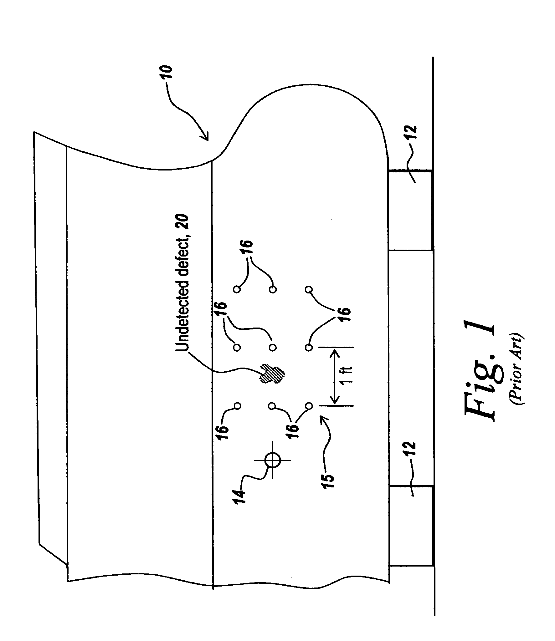
[0052]Referring now to FIG. 1, in the prior art, when a hull 10 is to be surveyed, it is hauled out at a dry-dock as symbolically illustrated by blocks 12. In order to perform the survey, a grid is mapped out on hull 10 relative to a fiducial point 14. The cross-points 16 on the grid are the points at which measurements are to be recorded.

[0053]Due to the difficulty of accurately locating measuring points relative to the fiducial point, a grid 15 is established across the hull mechanically by measuring rods or an overlay. However, due to the difficulty of providing a large number of measuring points on the hull, it is common to limit the number of measuring points by separating the measuring points 16 by one foot. It is assumed for surveying purposes that surveying the hull at these one-foot-spaced points is sufficient to be able to detect a defect 20, which defect could be a hull weakening, a hull wasting, deteriorating weld lines, or any other defect which would cause one to repai...


PUM


Abstract

An ultrasonic surveying method includes a network of transceivers adjacent the item to be surveyed to establish a reference plane and locating an array of pingers on the object to be surveyed to establish a survey plane, establishing by ranging from the pingers to the network the location of the survey plane, detecting relative motion between the network and the pingers and correcting survey measurements for the detected motion.

Description

RELATED APPLICATIONS[0001]This Application claims rights under 35 USC 119(e) from U.S. Provisional Application Ser. No. 60 / 517,948 filed Nov. 6, 2003, the contents of which are included herein by reference.FIELD OF THE INVENTION[0002]This invention relates to ultrasonic surveying and more particularly to a method for compensating for relative motion between an ultrasonic target and an ultrasonic detector.BACKGROUND OF THE INVENTION[0003]In the past, ship hull inspections have been required in order to obtain certification from governmental authorities as to the seaworthiness of the vessel.[0004]The most common way to obtain the governmental certificate is to dry-dock the vessel, an expensive process, and to both visually and ultrasonically inspect the hull of the vessel when it is in dry dock. The procedure takes the vessel out of service for as much as two weeks and requires as many as five to ten technicians in order to survey the hull.[0005]Typically in such a case, a surveying i...

Claims


Application Information

Patent Timeline
Patent Type & Authority Patents(United States)
IPC IPC(8): G01S3/80B63B9/00G01S5/30
CPCG01S5/30B63B9/00B63B71/00
Inventor GREELISH, STEPHEN JOHN
Owner SONICWORKS
Why Eureka
Try Eureka