Integrally damped composite aircraft floor panels

a composite aircraft and floor panel technology, applied in the direction of instruments, synthetic resin layered products, transportation and packaging, etc., can solve the problems of high radiation efficiency of floor panels, poor interior noise reduction effect, and ineffective noise reduction of light weight structural solutions, so as to achieve the effect of dampening vibrational nois

Active Publication Date: 2008-09-02
THE BOEING CO
View PDF26 Cites 58 Cited by
  • Summary
  • Abstract
  • Description
  • Claims
  • Application Information

AI Technical Summary

Benefits of technology

[0006]In accordance with the present invention an aircraft floor panel is provided comprising a honeycomb core element having an upper core surface, a lower core surface, and a core thickness. An upper face sheet assembly is mounted to and seals the upper core surface and includes at least one upper material sheet impregnated with an upper epoxy resin. A lower damping face sheet assembly is mounted to and seals the lower core surface and includes at least one lower material sheet infused with a highly damped lower epoxy resin. The lower damping face sheet assembly dampens vibrational noise.

Problems solved by technology

These very light weight structural solutions are typically not efficient at reducing noise that transmits through them.
The floor panels, therefore, have a high radiation efficiency which is bad for interior noise.
This approach adds extra weight, fabrication costs, and installation costs to the floor panel design.

Method used


Image

  • Integrally damped composite aircraft floor panels
  • Integrally damped composite aircraft floor panels
  • Integrally damped composite aircraft floor panels

Examples


third embodiment

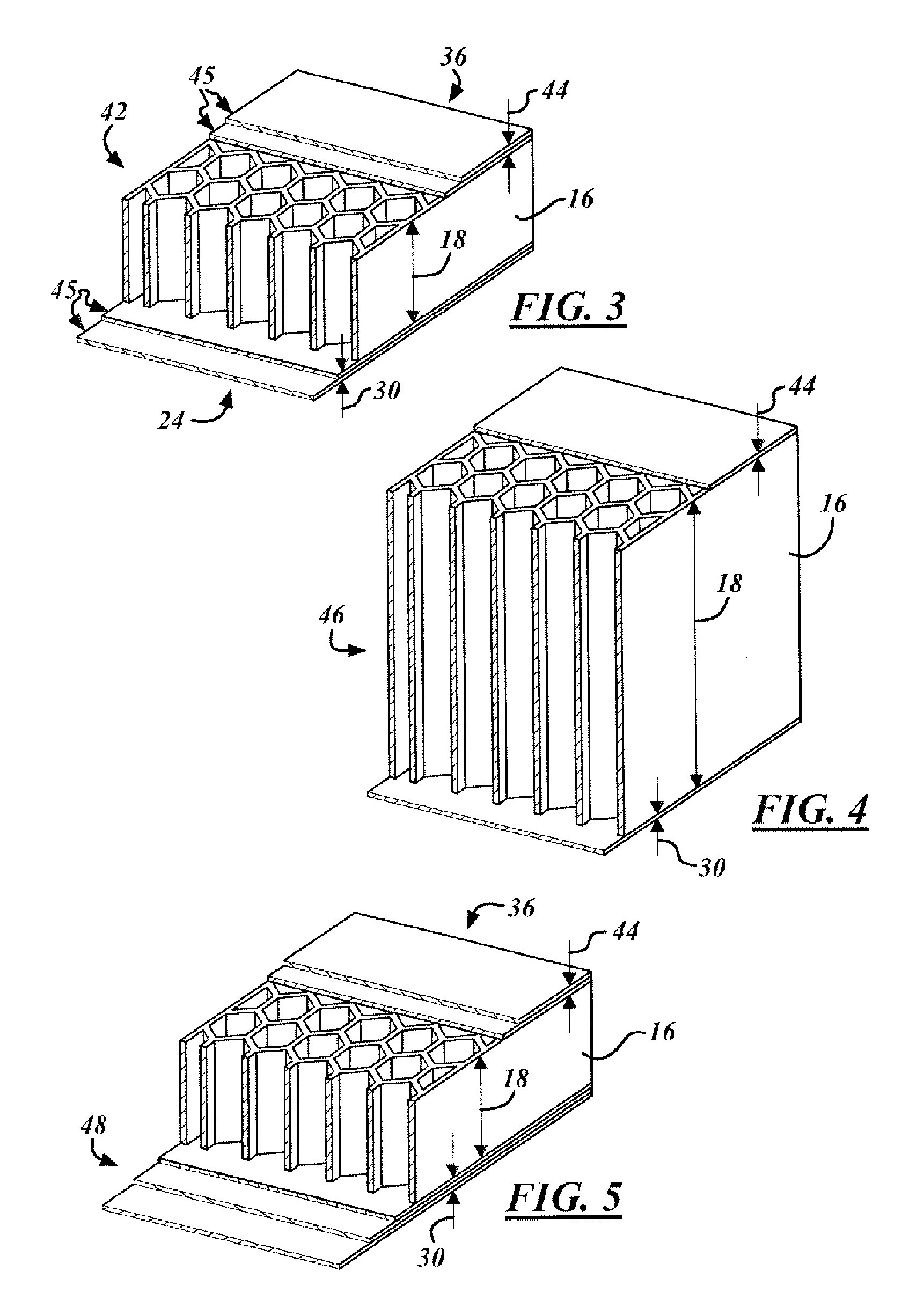
[0019]A third embodiment is illustrated in FIG. 4 which may be referred to as the thick core 46 embodiment. In this embodiment the core thickness 18 was increased to approximately 1.25 inches. The upper and lower sheet thicknesses 30, 44 were kept at 0.017 inches apiece (preferably comprised of 2-ply 3k-70-PW cloth at 0.085 inches per ply). By increasing the core thickness 18 while retaining original sheet widths 30, 44 the flex load was found to be 269 lbs and the deflection at 100 lbs was found to be 0.2 inches. It should be understood that all test data in this patent is for illustrative purposes only in regards to the improvement of damping and flex characteristics.

fourth embodiment

[0020]Finally a fourth embodiment is illustrated in FIG. 5, which may be referred to as the mixed face sheet 48 embodiment. In the mixed face sheet 48 embodiment, the upper face sheet 36 is comprised of a high strength face sheet while the lower face sheet 24 is a low strength damping face sheet. The high strength face for example can be comprised of carbon / graphite tape laminate such as sold by Hexcel Corporation under the trade name AS4 / Magnamite. In this embodiment the core thickness 18 may remain the same, but the upper face sheet 36 is preferably comprised of grade 190 tape with plies of 0 / 90 at 0.0075 inches combined to arrive at a upper sheet width 44 of 0.017 inches. The lower damping face sheet 24 is comprised of 0.024 inches of carbon / epoxy cloth such as the 3k-70-PW cloth (preferably comprised of 3 plies of 0.0085 cloth) impregnated with a two part epoxy resin with superior flexibility at low temperatures. This combination of upper face rigidity with lower face flex provi...


PUM

PropertyMeasurementUnit
thicknessaaaaaaaaaa
thicknessaaaaaaaaaa
cell sizeaaaaaaaaaa

Abstract

In accordance with the present invention an aircraft floor panel is provided comprising a honeycomb core element having an upper core surface, a lower core surface, and a core thickness. An upper face sheet assembly is mounted to and seals the upper core surface and includes at least one upper material sheet impregnated with an upper epoxy resin. A lower damping face sheet assembly is mounted to and seals the lower core surface and includes at least one lower material sheet infused with a highly damped lower epoxy resin. The lower damping face sheet assembly dampens vibrational noise.

Description

TECHNICAL FIELD[0001]The present invention relates generally to an apparatus and method for the damping of aircraft interior floor panels, and more particularly to an apparatus and method for integrating such damping directly into composite aircraft floor panels.BACKGROUND OF THE INVENTION[0002]Commercial aircraft must not only meet strength, weight and cost objectives they must also be designed to achieve adequate customer satisfaction. One arena of customer satisfaction arises regarding passenger comfort. The reduction of interior noise levels is considered critical to passenger comfort. A wide variety of noise sources come from many locations outside and inside the airframe. Aircraft design benefits are achieved by addressing these noise sources and minimizing their impact on passengers.[0003]One known noise source into the main cabin is through the aircraft floor panels. The floor panels are typically constructed using lightweight designs with high rigidity. These very light wei...

Claims


Application Information

Patent Timeline
Patent Type & Authority Patents(United States)
IPC IPC(8): G10K11/16E04B1/84G10K11/168G10K11/04
CPCB32B3/12B64C1/18B32B5/26B32B27/38B32B2605/18B32B2260/021B32B2260/023B32B2260/046B32B2262/0269B32B2262/101B32B2262/106B32B2307/102B32B2307/54B32B2307/56B32B2419/04B32B2605/003
Inventor LIGUORE, SALVATORE L.MONTGOMERY, JOSHUA M.YOUNIE, MARK L.RACKL, ROBERT G.
Owner THE BOEING CO
Why Eureka
Try Eureka