
Lighting or indicator device, in particular for motor vehicles

a technology of light or indicator device and motor vehicle, which is applied in the direction of lighting support device, fixed installation, lighting and heating apparatus, etc., can solve the problems of relatively high cost and relatively complex process implementation, and achieve the effect of simple, inexpensive and reliabl

Active Publication Date: 2008-09-02
VALEO VISION SA
View PDF25 Cites 23 Cited by
  • Summary
  • Abstract
  • Description
  • Claims
  • Application Information

AI Technical Summary

Benefits of technology

[0023]This invention lies within this context and relates to the provision of a lighting or indicator device which can easily have an aspect in three dimensions matching the external geometry of the lighting or indicator device in a simple, inexpensive and reliable way, while retaining the advantages of a plane which is common to two dimensions for attachment of the light sources.

Problems solved by technology

Such a process is relatively complex to implement, and requires thorough investigation of the location of the lamp to determine the lines for folding the base for its electrical power circuit.
It follows that the lighting or indicator devices so obtained offer greater development possibilities for the stylists, but have relatively high costs which restrict their use to top-of-the-range vehicles.

Method used


Image

  • Lighting or indicator device, in particular for motor vehicles
  • Lighting or indicator device, in particular for motor vehicles
  • Lighting or indicator device, in particular for motor vehicles

Examples


first embodiment

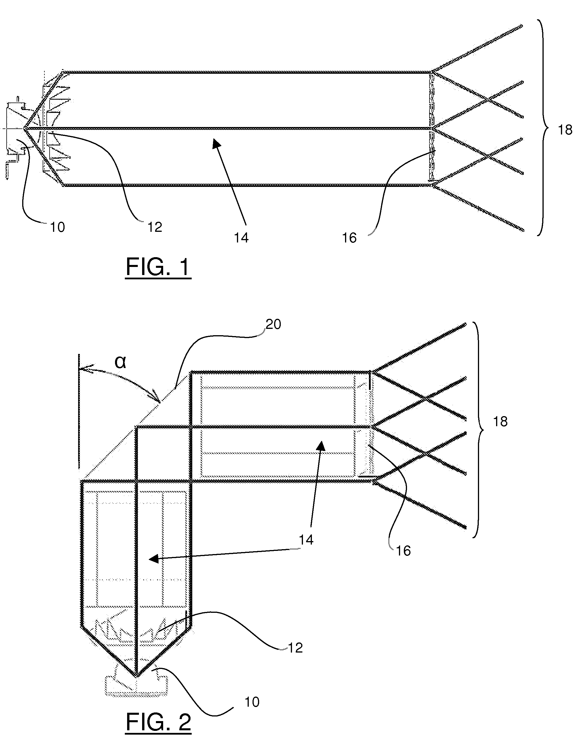
[0060]Various embodiments may be envisaged for the devices in FIG. 1 or 2. In accordance with the first embodiment the input optical system 12 is of one piece with output optical system 16. The volume between input optical system 12 and output optical system 16 is thus formed of the same transparent material as the input and output optical system 16. The lighting or indicator device is thus constructed of a single three-dimensional optical component forming a monobloc module whose transverse cross-section will be advantageously circular, but may also be of a polygonal shape, preferably symmetrical with respect to the optical axis of the device.

[0061]The transparent material used may for example comprise polycarbonate (PC) or polymethylmethacrylate (PMMA), or again glass.

[0062]In this embodiment the input and output optical systems are formed on the extreme surfaces of the volume. The collimating element comprising the input optical system may for example be formed through a concave ...

second embodiment

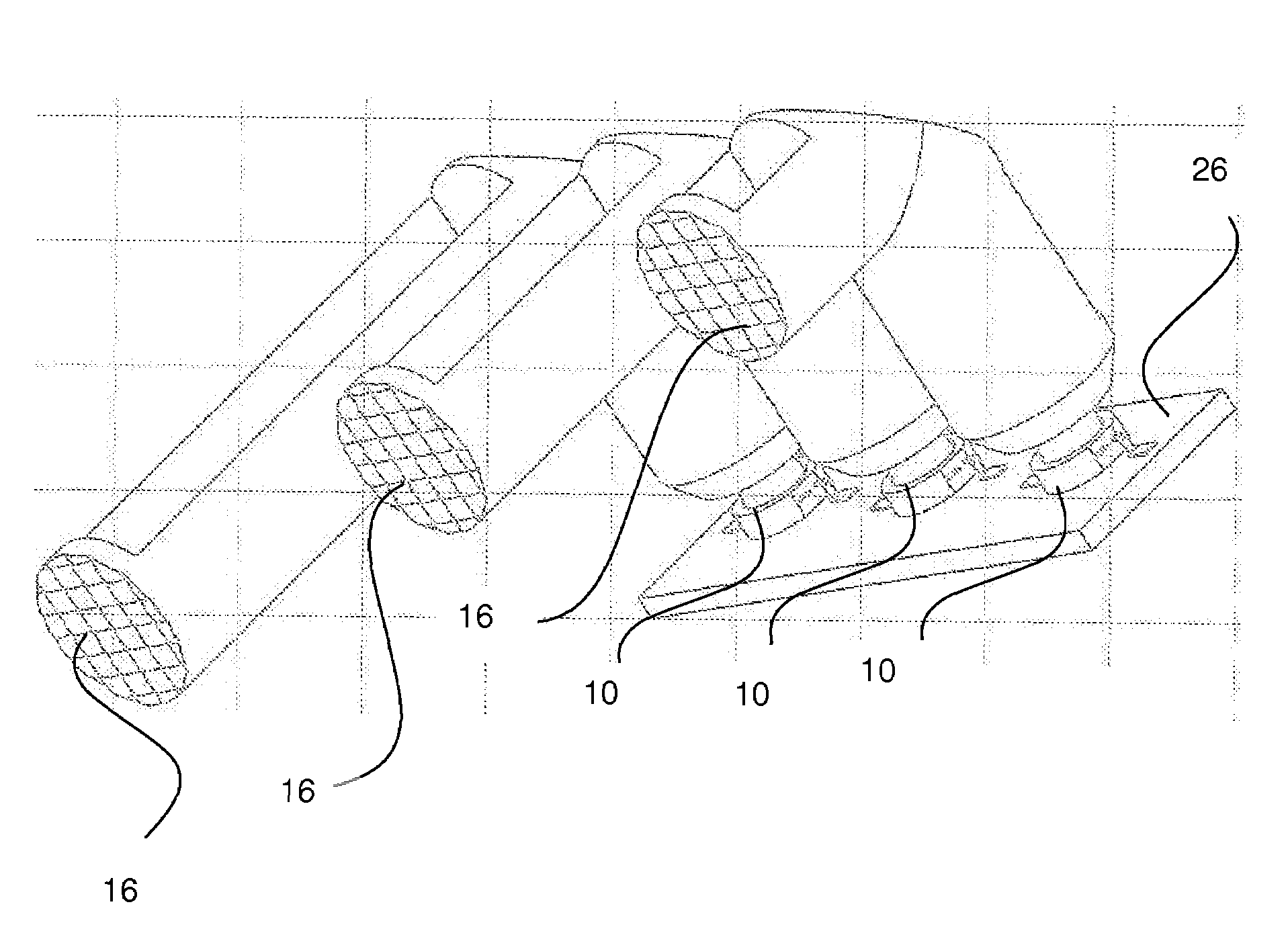
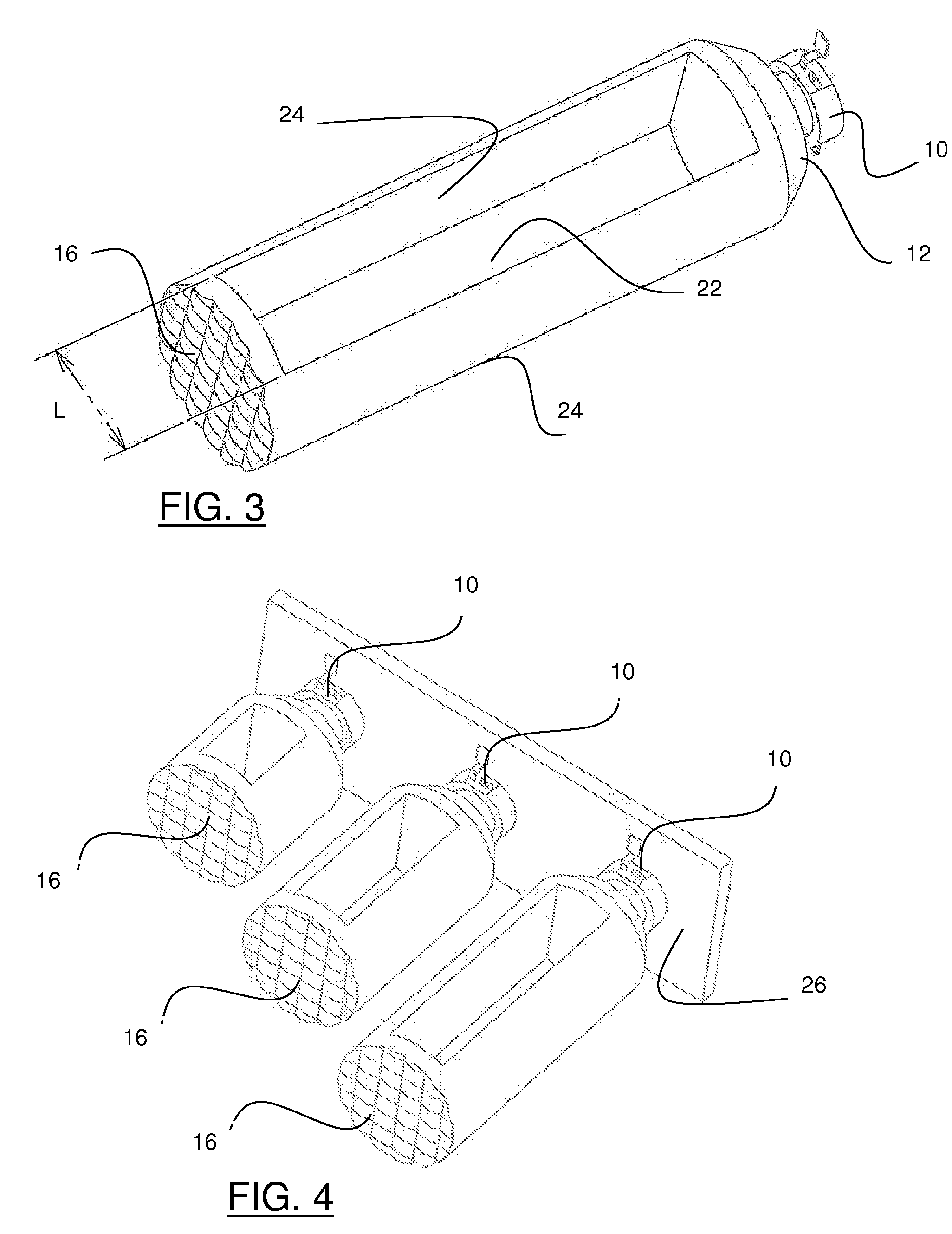
[0065]In accordance with the second embodiment, the input 12 and output 16 optical systems are separated and separate from one another. The volume between the input 12 and output 16 optical systems thus comprises air. In this case the input and output optical systems may be wholly independent of each other, and each supported by a supporting member which ensures that they have a relatively fixed position, in particular aligned with the optical axis of the device. They may also be located at the extremities of the three-dimensional optical piece in the preceding embodiment, this piece having been hollowed out at 22, as shown in FIG. 3, to form a hollow module.

[0066]Void 22 may be formed in any appropriate way, the input and output optical systems being both supported by at least one arm 24, two in the example illustrated, connecting the input and output optical systems. The width L of void 22 is selected to ensure that arms 24 have minimum rigidity. In the example illustrated in FIG....


PUM


Abstract

This invention relates to a lighting or indicator device, in particular for motor vehicles, comprising at least one light source and at least one output optical system in order to form a lighting or indicator lamp beam consistent with regulations. In accordance with this invention the device comprises at least one input optical system comprising a collimating element receiving light rays emitted by the source and transmitting a beam of parallel rays towards an output optical system which forms a lighting or indicator lamp beam.

Description

BACKGROUND OF THE INVENTION[0001]I. Field of the Invention[0002]This invention relates to lighting or indicator devices intended for motor vehicles in particular. Lighting devices mainly comprise the lamps for dipped, main, fog or running lamps, and the indicator lamps mainly comprise position lamps, direction change indicator lamps, braking indicator lamps, reversing lamps, and rear fog lamps.[0003]In order to simplify location of these various devices on a vehicle it is normal practice to group several together in a single housing, which in particular makes it easier to install them on the vehicle, and to connect them to the vehicle's electrical loom using a single connector provided with an appropriate number of terminals.[0004]Each function generally incorporates a light source, a reflector reflecting the light rays emitted by the source in a general direction of emission, and possibly an enclosing glass, also called an indicator, which may or may not contribute to formation of ...

Claims


Application Information

Patent Timeline
Patent Type & Authority Patents(United States)
IPC IPC(8): F21V13/04F21Y101/00
CPCF21S48/215F21S48/2212F21S48/2237F21S48/225F21S48/2262G02B6/0018F21S48/236F21V5/045F21V7/0091G02B6/0016F21S48/2281F21V7/0008F21S43/14F21S43/26F21S43/237F21S43/241F21S43/243F21S43/249F21S43/315
Inventor GASQUET, JEAN-CLAUDE
Owner VALEO VISION SA
Learn More