Power train for use in motor vehicles and the like

a technology for motor vehicles and power trains, applied in the direction of fluid actuated clutches, clutches, non-mechanical actuated clutches, etc., can solve the problems of invariably undesirable motor vehicle performance, not only bulky, complex and expensive, etc., and achieve the effect of simple, inexpensive and reliabl

Inactive Publication Date: 2005-01-11
SCHAEFFLER TECH AG & CO KG
View PDF21 Cites 5 Cited by
  • Summary
  • Abstract
  • Description
  • Claims
  • Application Information

AI Technical Summary

Benefits of technology

An object of the present invention is to provide a novel and improved power train, particularly for use in motor vehicles, wherein the aforediscussed problems and drawbacks of conventional power trains are overcome or at least partially alleviated in a simple, inexpensive and reliable manner.
The at least one cylinder can be provided with a stop serving to limit the extent of movability of the piston in such cylinder in the direction of the predetermined axis in order to change the condition of the friction clutch.

Problems solved by technology

This creates problems when the output member of the prime mover must be realigned with the input member of the change speed transmission, an undertaking which must be carried out rather frequently in the power trains of motor vehicles.
It is well known that the crankshaft or another rotary output member of the engine in the power train of a motor vehicle invariably performs undesirable stray (such as wobbling and / or axial) movements which must be taken up by the slave cylinder and at least a percentage of which is transmitted from the slave cylinder to the means (such as a pipe and a master cylinder) which is provided to supply pressurized fluid (such as oil or another hydraulic fluid) to the chamber or chambers of the housing (cylinder) of the slave cylinder.
The stray movements of the slave cylinder are felt by the operator of the vehicle, namely as vibrations of the clutch pedal, and are or can constitute a cause of considerable discomfort.
A drawback of presently known antivibration units is that they are not only bulky, complex and expensive but that they are also far from being a reliable and versatile means for solving the above-enumerated problems.
They normally rely upon a throttling action, i.e., they are intended to throttle the undesirable stray movements and / or dampen the noises, they establish space-requiring dead volumes for bodies of fluid and / or they employ expensive materials and / or resort to complex and expensive procedures for the making of several parts in the force transmitting system between the actuator (such as a fluid-operated or electrical actuator means) and one or more parts (such as a diaphragm spring or another resilient element) of the friction clutch.

Method used


Image

  • Power train for use in motor vehicles and the like
  • Power train for use in motor vehicles and the like
  • Power train for use in motor vehicles and the like

Examples


Embodiment Construction

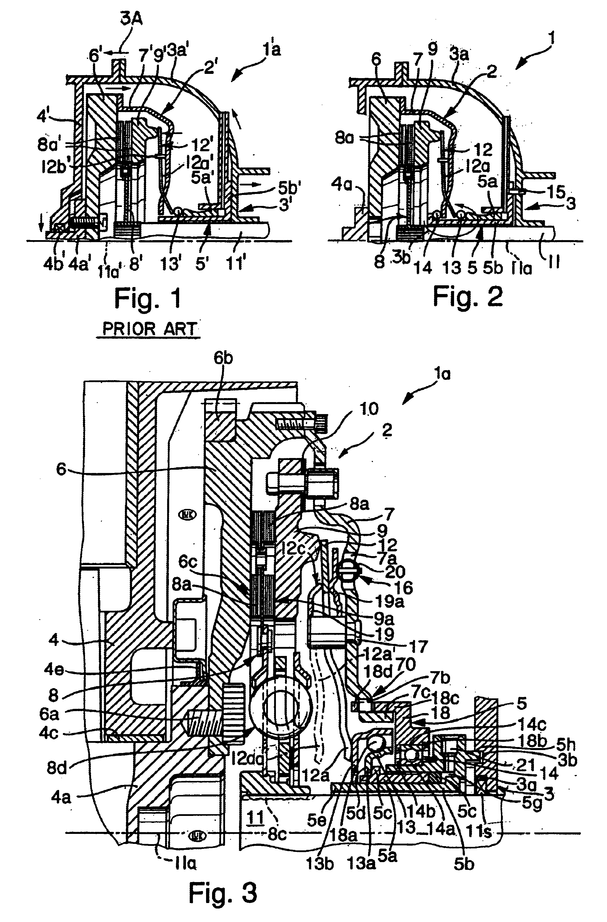
FIG. 1 shows a portion of a conventional power train 1′ which can be put to use in a motor vehicle to drive the front and / or the rear wheels. This power train comprises a prime mover, such as an internal combustion engine, having a body or housing 4′ and a rotary output member 4a′ (such as the crankshaft or the camshaft of the engine) which is journalled in an antifriction bearing 4b′ (such as a ball or roller bearing) mounted in the housing 4′. The output member 4a′ serves to drive an input member 11′ by way of an engageable and disengageable friction clutch 2′.

The input member 11′ constitutes the input shaft of a change-speed transmission 3′ having a bell-shaped housing or case 3a′ affixed to the engine housing 4′. The clutch 2′ includes a pressure plate 9′ which is coaxial with a counterpressure plate 6′ and is biased by a diaphragm spring 12′. When the clutch 2′ is engaged, the diaphragm spring 12′ is free or is compelled to bias the pressure plate 9′ against the adjacent fricti...


PUM


Abstract

A power train for use in motor vehicles has a friction clutch including a housing which rotates with the output shaft of the engine and a clutch disc which transmits torque to the input shaft of a change-speed transmission in the engaged condition of the clutch. The clutch can be engaged and / or disengaged by one or more slave cylinders which is or are rotatably mounted on and is or are being held against axial movement relative to the clutch housing. At least one release bearing can be installed between the piston(s) of the slave cylinder(s) and the diaphragm spring of the friction clutch, and a second bearing is or can be installed between the slave cylinder housing(s) and the clutch housing.

Description

CROSS-REFERENCE TO RELATED CASESThis application claims the priority of the commonly owned copending German patent application Serial No. 100 40 168.6 filed Aug. 17, 2000. The disclosure of the above-referenced priority application, as well as that of each US and foreign patent and patent application identified in the specification of the present application, is incorporated herein by reference.BACKGROUND OF THE INVENTIONThis invention relates to improvements in power trains, especially for use in motor vehicles. More particularly, the present invention relates to improvements in power trains of the type wherein a rotary output member of a prime mover, such as the crankshaft or the camshaft of the engine in a motor vehicle, serves to transmit torque to the rotary input member of a driven unit (e.g., to the input shaft of the change-speed transmission in the power train of a motor vehicle) by way of a friction clutch. Still more particularly, the present invention relates to improvem...

Claims


Application Information

Patent Timeline
Patent Type & Authority Patents(United States)
IPC IPC(8): F16D25/08
CPCF16D25/083
Inventor REIK, WOLFGANGRAMMHOFER, THOMASZINK, MATTHIAS
Owner SCHAEFFLER TECH AG & CO KG
Why Eureka
Try Eureka