Active balun device

a balun device and balun technology, applied in the direction of amplifiers with semiconductor devices only, differential amplifiers, amplifiers with semiconductor devices/discharge tubes, etc., can solve the problems of significant affecting the bandwidth and the great change in phas

Inactive Publication Date: 2008-09-02
ELECTRONICS & TELECOMM RES INST
View PDF14 Cites 50 Cited by
  • Summary
  • Abstract
  • Description
  • Claims
  • Application Information

AI Technical Summary

Problems solved by technology

In this case, a change in bias of the transistors connected to the respective inputs and a change in a process leads to a great change in a phase and significantly affects the bandwidth.

Method used


Image

  • Active balun device
  • Active balun device
  • Active balun device

Examples


Embodiment Construction

[0016]Hereinafter, an exemplary embodiment of the present invention will be described in detail. However, the present invention is not limited to the embodiments disclosed below, but can be implemented in various types. Therefore, the present embodiment is provided for complete disclosure of the present invention and to fully inform the scope of the present invention to those ordinarily skilled in the art.

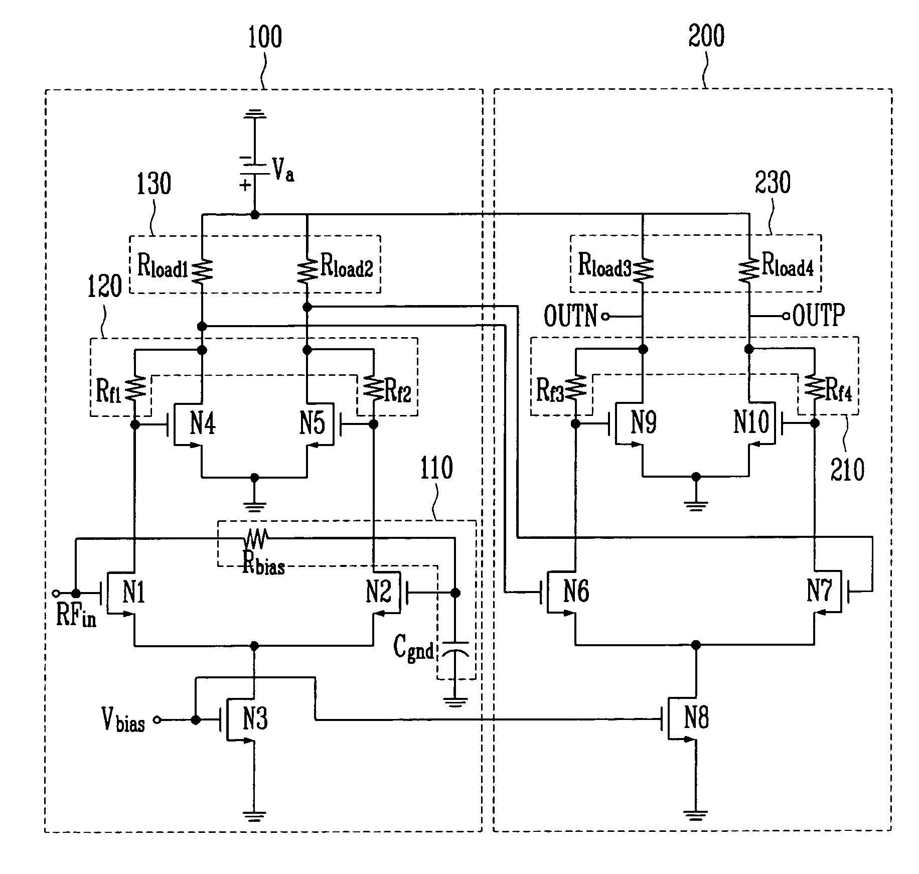
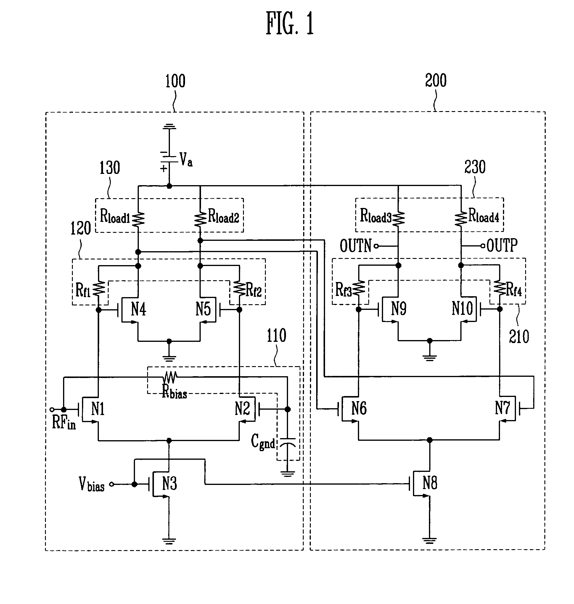
[0017]FIG. 1 is a circuit diagram of an active balun device according to an embodiment of the present invention.

[0018]Referring to FIG. 1, the active balun device according to an embodiment of the present invention includes a differential input portion 100 for receiving an external single radio frequency (RF) input signal, i.e., a single-ended RF input signal RFin to output two complementary differential signals; and a differential amplifier 200 connected to the differential input portion 100 in cascade for amplifying the two differential signals received from the differential inpu...


PUM


Abstract

An active balun device is provided. The active balun device includes: a differential input portion for receiving an external single input signal to output two complementary differential signals; and a differential amplifier connected to the differential input portion in cascade to amplify the two differential signals received from the differential input portion. Thus, the active balun device has a sufficient gain and a desired bandwidth in a semiconductor circuit.

Description

CROSS-REFERENCE TO RELATED APPLICATION[0001]This application claims priority to and the benefit of Korean Patent Application No. 2005-89721, filed on Sep. 27, 2005, the disclosure of which is incorporated herein by reference in its entirety.BACKGROUND[0002]1. Field of the Invention[0003]The present invention relates to an active balun device, and more particularly, to an active balun device having a sufficient gain and a desired bandwidth in a semiconductor circuit.[0004]2. Discussion of Related Art[0005]Generally, a common source field effect transistor (FET) and a common gate FET are widely used to constitute a wide-band amplifier, characteristics of which are very sensitive to processes and parasitic elements.[0006]In a conventional active balun device, an input signal is provided to sources and gates of common gate and source FETs, and an output signal is derived at drains of the FETs. The signal input to the source is in phase with the output signal at the drain while the signa...

Claims


Application Information

Patent Timeline
Patent Type & Authority Patents(United States)
IPC IPC(8): H03F3/04
CPCH03F3/189H03F3/68H03F3/45183H03F3/45H03F1/42
Inventor LEE, YOUNG JAEYU, HYUN KYU
Owner ELECTRONICS & TELECOMM RES INST
Why Eureka
Try Eureka