Multi-beam antenna with shared dielectric lens

a dielectric lens and antenna technology, applied in the field of antennas, can solve the problems of occupying a significant amount of space on a vehicle by separating antennas, and being relatively expensiv

Inactive Publication Date: 2008-09-02
GM GLOBAL TECH OPERATIONS LLC
View PDF6 Cites 182 Cited by
  • Summary
  • Abstract
  • Description
  • Claims
  • Application Information

AI Technical Summary

Benefits of technology

[0007]In forming the multi-beam antenna in this way, the Applicants have found that the shape and angular direction of the radiation beams of the antenna can be adjusted based upon the physical and dielectric characteristics of the lens, the position of the feed apertures along the surface of the dielectric lens, and the selected frequencies at which electromagnetic energy propagates in the waveguide feeds.
[0017]Accordingly, an inexpensive, integrated multi-beam antenna that satisfies the angular coverage requirements of the short and long range radars of the above described automotive radar safety system is realized.

Problems solved by technology

These separate antennas take up a significant amount of space on a vehicle, and can be relatively expensive as compared to other radar system components.

Method used


Image

  • Multi-beam antenna with shared dielectric lens
  • Multi-beam antenna with shared dielectric lens
  • Multi-beam antenna with shared dielectric lens

Examples


Embodiment Construction

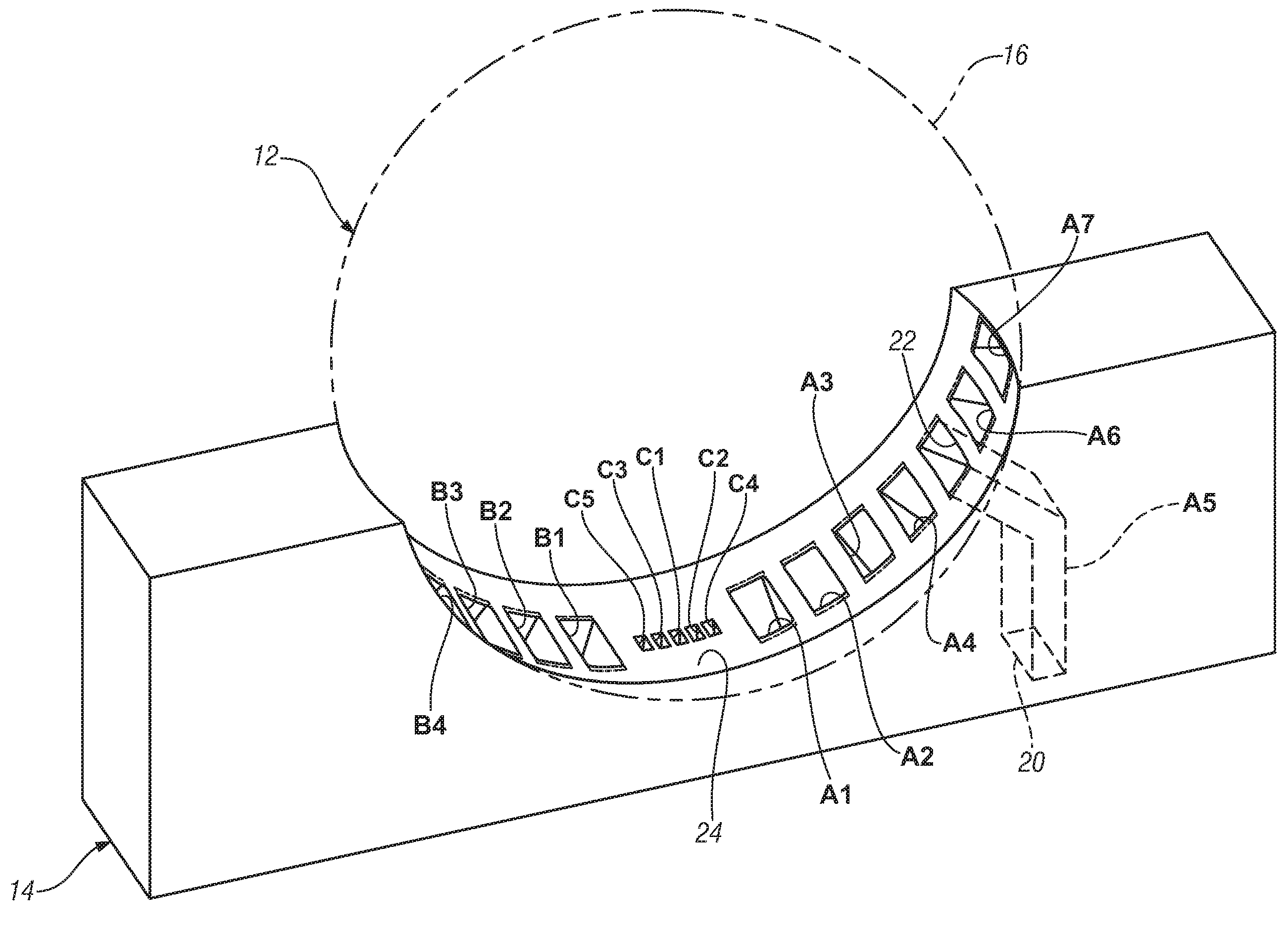
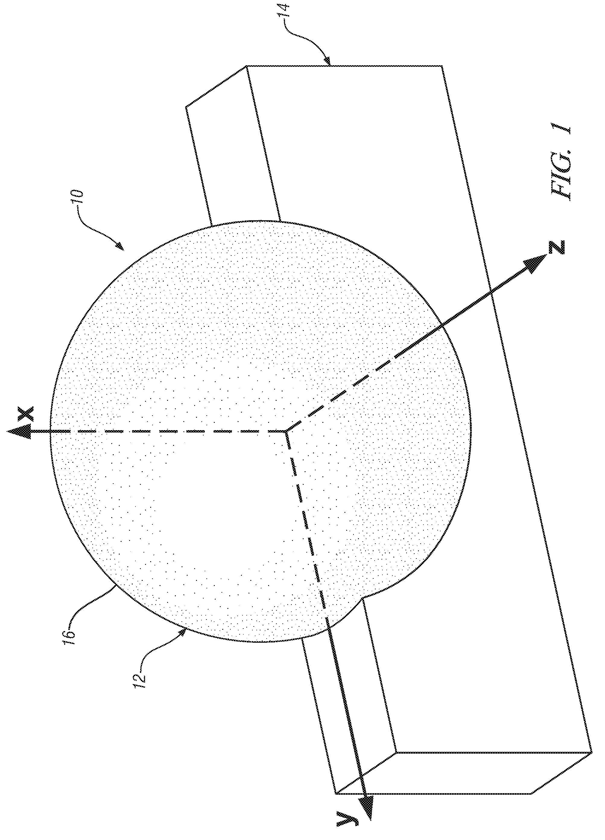
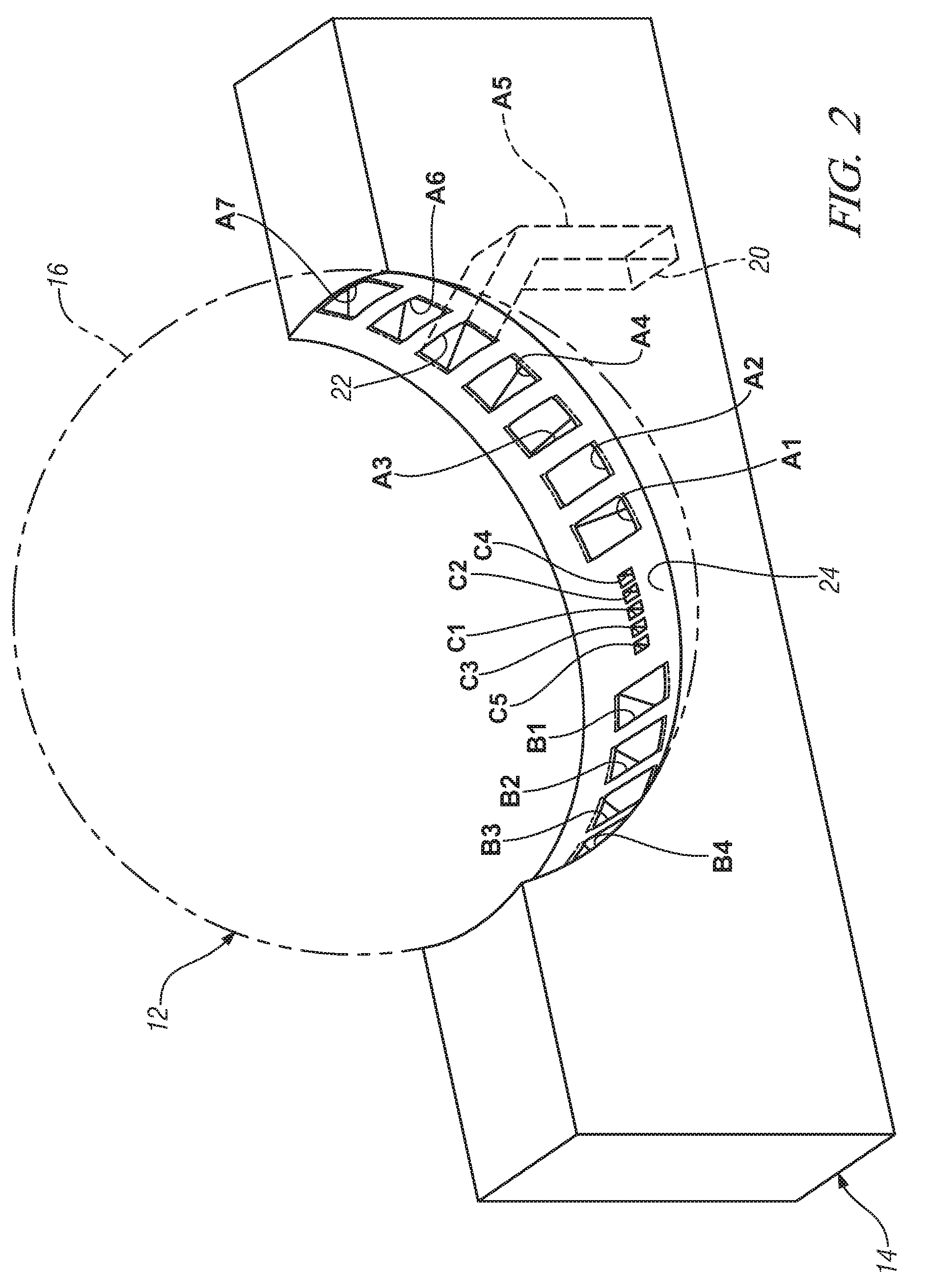
[0025]A Luneburg lens is a spherical lens formed of a non-homogeneous medium, which is known to have perfect focusing properties. One form of the Luneburg lens has a relative dielectric constant of ∈r=2 at its center, which gradually decreases to ∈r=1 as its outer surface in accordance with the relationship ∈r=2−R2, where R represents the radial distance from the center of a unit radius sphere. This type of lens is known to have one focal point on its spherical surface, with the other focal point at infinity in a direction away from the opposite side of the sphere on a line defined by the surface focal point and the sphere center. Perfect Luneburg lens are difficult to make in practice, and approximate versions having stepped changes in their dielectric constant formed by concentric hemispherical shells of different dielectrics are known in the art; however, these configurations are relatively expensive to manufacture.

[0026]The Applicants have recognized that a solid spherical diele...


PUM


Abstract

An integrated multi-beam antenna with a shared dielectric lens is disclosed. The antenna is formed by positioning the feed apertures of a plurality of waveguide feeds at positions located on the surface of the shared dielectric lens. The angular direction and shape of radiation beams produced by the waveguide feeds are determined by the physical and dielectric characteristics of the lens, the location of feed apertures of the waveguide feeds on the surface of the lens, and the frequency of electromagnetic energy propagating in the waveguide feeds. The principles of the invention are applied to realize an inexpensive, integrated multi-feed antenna adapted to provide desired angular areas of coverage for both a long range and short range radar in an automotive radar safety system.

Description

CROSS REFERENCE TO RELATED APPLICATIONS[0001]This application claims priority to US provisional patent application Ser. No. 60 / 805,620 filed on Jun. 23, 2006 which is hereby incorporated herein by reference.TECHNICAL FIELD[0002]The present invention is related to antennas, and more particularly, to a multi-beam antenna having a shared dielectric lens.BACKGROUND OF THE INVENTION[0003]Radar based safety systems for automobiles require directional antennas capable of distinguishing targets in a wide field of view in front of vehicles. It has been found advantageous to provide such safety systems with both short and long range radar coverage, where the antenna requirements differ for each type of radar coverage. For long range radar coverage extending from about −7.5° to about 7.5° in azimuth in front of a vehicle, radar antenna beamwidths of about 3° to 4° have been found effective for radiation beams in this angular area of coverage. For short range radar coverage extending from about...

Claims


Application Information

Patent Timeline
Patent Type & Authority Patents(United States)
IPC IPC(8): H01Q19/06
CPCH01Q25/007H01Q19/062
Inventor COLBURN, JOSEPH S.HSU, HUI-PINALTAN, OSMAN D.
Owner GM GLOBAL TECH OPERATIONS LLC
Why Eureka
Try Eureka