Method and apparatus for situation recognition using optical information

a technology of optical information and situation recognition, applied in the field of situation recognition, can solve the problems of limited measurement results which can be acquired from the surrounding environment by the laser-range finder, difficult to identify robots, and insufficient sparseness

Inactive Publication Date: 2008-09-02
SONY CORP +1
View PDF1 Cites 10 Cited by
  • Summary
  • Abstract
  • Description
  • Claims
  • Application Information

AI Technical Summary

Benefits of technology

[0038]The technique disclosed in Non-Patent Document 7 uses similarity between images captured by a wide field-of-view camera. However, the technique removes information about the orientation of captured images in order to maximize the similarity between the images. This calculation puts a heavy burden on a processor. There may be a case where it is reasonable to aim at maximization of the effectiveness of a given database of training video at the sacrifice of discrimination ability for orientation. However, it is apparent in practice that how many examples for training should be collected is not a problem, but how accurately similar locations or situations can be identified is important. Once an actual system is built, new training examples are easily acquired.
[0052]According to the present invention, it is possible to provide an apparatus, a method, a computer program and a recording medium, all of which can recognize a current situation by matching with history in a certain time period into account, instead of comparing simple temporal moments when matching a past situation and a current situation by using optical information, and / or a system equipped with the apparatus, the method, the computer program or the recording medium.

Problems solved by technology

This is because if a robot provided with the above-mentioned conventional system stays at one location, measurement results which can be acquired from the surrounding environment by the laser-range finder are limited and are too sparse.
Namely, because of inherent limitations of device characteristics of the laser-range finders, the location of the robot is difficult to identify with a measurement result acquired at one location, and additional information is necessary for more accurate identification.

Method used


Image

  • Method and apparatus for situation recognition using optical information
  • Method and apparatus for situation recognition using optical information
  • Method and apparatus for situation recognition using optical information

Examples


Embodiment Construction

[0072]Embodiment of the present invention will be described below in detail with reference to the accompanying drawings.

[0073]According to one embodiment of the present invention, there is provided a situation recognition apparatus 1 capable of associating a current situation with a past situation while taking into account context related to a time sequence of optical information acquired sequentially.

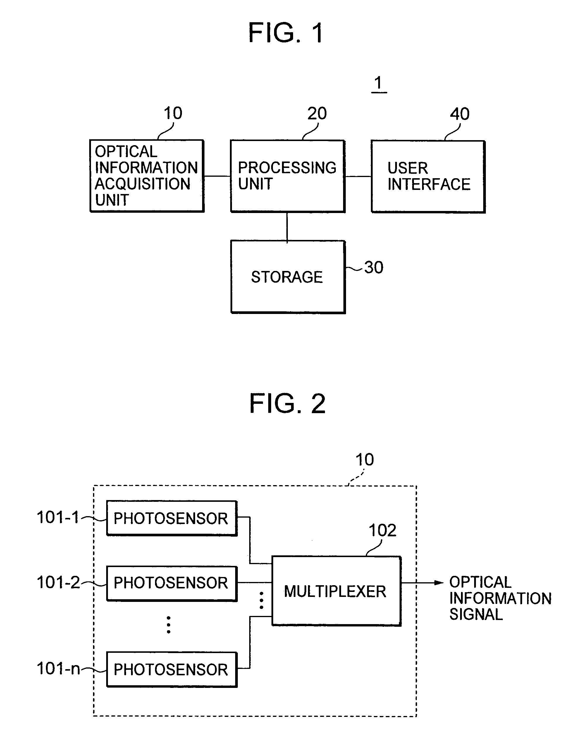
[0074]The situation recognition apparatus 1 includes, as shown in FIG. 1 by way of example, an optical information acquisition unit 10 which acquires optical information and provides an output, a processing unit 20 which carries out predetermined processing on the output and performs situation recognition, a storage 30 which records information necessary for the predetermined processing, and a user interface 40 which presents a result of the situation recognition to a user as well as accepts operation inputs from the user. The processing unit 20, the storage 30 and the user interface 4...


PUM


Abstract

A situation recognition apparatus includes: an optical information acquisition unit configured to acquire optical information; a storage configured to store a plurality of pieces of optical information; a processing unit configured to match a plurality of the pieces of optical information stored in the storage and optical information newly acquired by the optical information acquisition unit; and an output unit configured to output a result of the matching. The storage further stores a probabilistic model that numerically represents transitions between the plurality of pieces of optical information.

Description

BACKGROUND OF THE INVENTION[0001]1. Field of the Invention[0002]The present invention relates to a method and apparatus for situation recognition, a system, a computer program, and a recording medium and, more particularly, to a situation recognition method and apparatus for recognizing a situation by comparing the current and past situations by using optical information, a system, a computer program, and a recording medium.[0003]2. Description of Related Art[0004]In a technical field of robotics, there is a case where a parabolic camera having a 360° field of view and image recording techniques are combined to perform location measurement on a robot, as described in the following non-patent documents 2 to 4 by way of example. Such technology performs detailed calibration processing for associating an acquired image or image group with a particular point in a reference image database space called an image atlas.[0005]Matching of images which is performed for the above-mentioned asso...

Claims


Application Information

Patent Timeline
Patent Type & Authority Patents(United States)
IPC IPC(8): G06K9/00G06T7/00G06V20/00
CPCG06K9/00624G06V40/20G06V20/00G06V10/85G06F18/295G06T7/00G06V10/10
Inventor CLARKSON, BRIANMURATAKOJIMA, TAMAKIZHAO, WENWU
Owner SONY CORP
Why Eureka
Try Eureka