Harmonic drive camshaft phaser

a camshaft and phaser technology, applied in the direction of machines/engines, couplings, machine/engines, etc., can solve the problems of sluggish response of conventional cam phasers at low engine speed, large oil pump requirements, and difficult pumping and supply of phasers

Active Publication Date: 2008-09-09
DELPHI TECH IP LTD
View PDF20 Cites 73 Cited by
  • Summary
  • Abstract
  • Description
  • Claims
  • Application Information

AI Technical Summary

Problems solved by technology

First, at low engine speeds engine oil pressure tends to be low, and sometimes unacceptably so; therefore, the response of conventional cam phasers is sluggish at low engine speeds.
Second, at low environmental temperatures, and especially at engine start-up, engine oil displays a relatively high viscosity and is more difficult to pump and to supply to a phaser in a rapid-response fashion.
Third, using engine oil to drive a phaser is parasitic on the engine oil system and can lead to requirement for a larger oil pump.
And finally, for fast actuation, a larger engine oil pump may be necessary, resulting in an additional energy drain on the engine.

Method used


Image

  • Harmonic drive camshaft phaser
  • Harmonic drive camshaft phaser
  • Harmonic drive camshaft phaser

Examples


Embodiment Construction

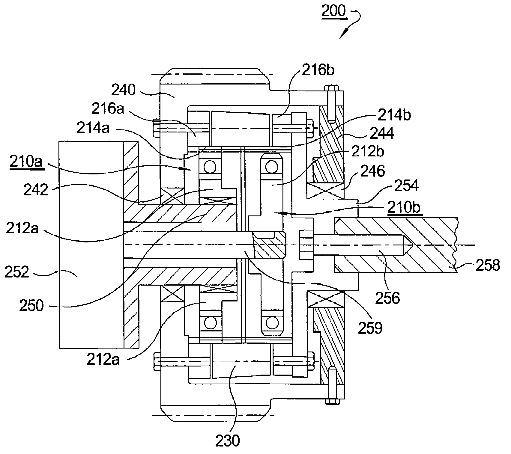
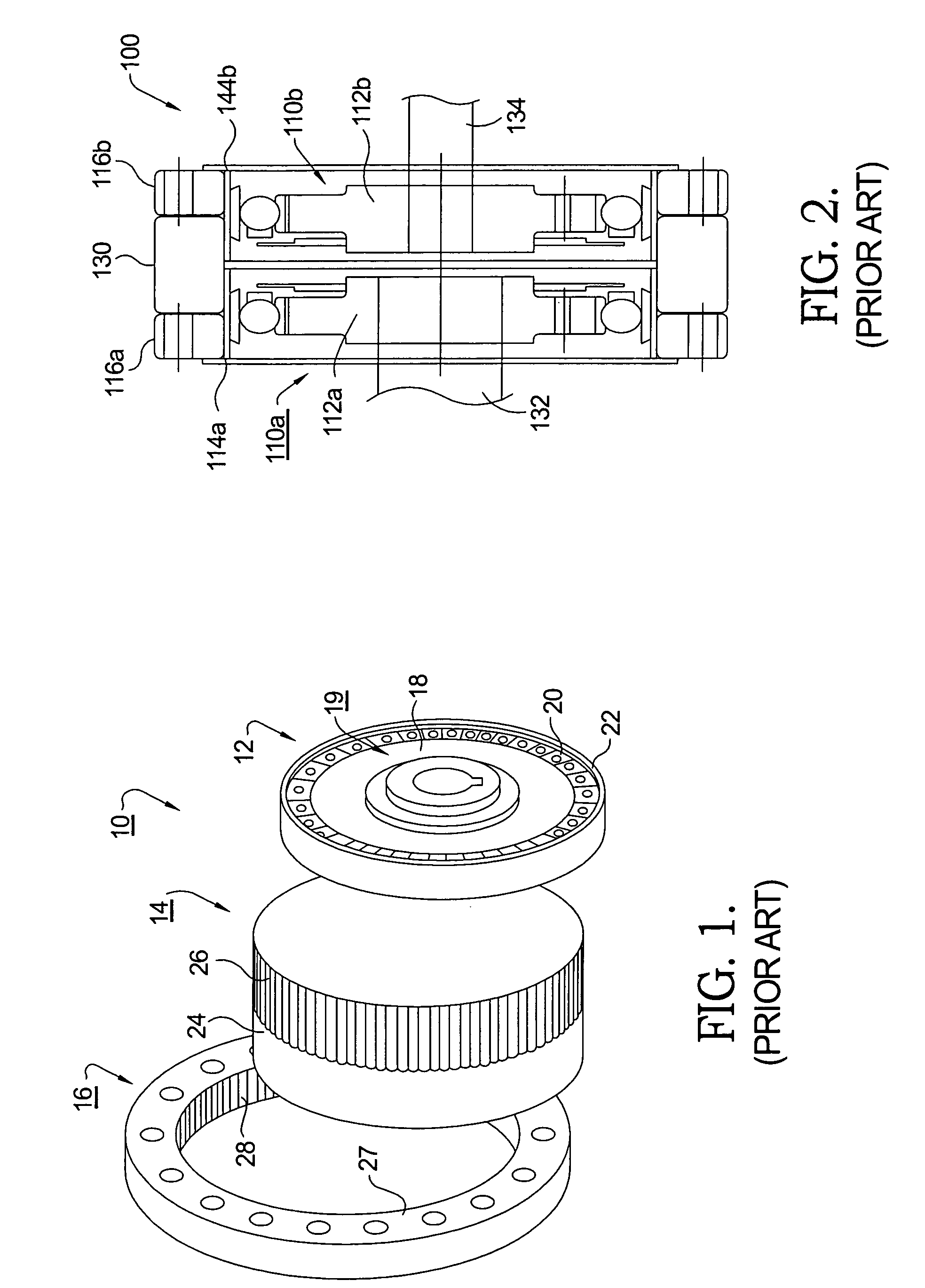
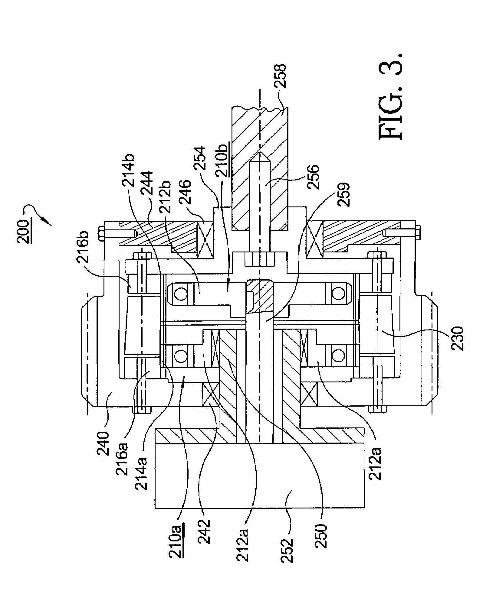
[0024]Referring to FIG. 1, a harmonic gear drive unit 10 comprises a wave generator 12, a flexspline 14, and a circular spline 16.

[0025]WG 12 is an assembly of an elliptical steel disc 18 supporting an elliptical bearing 20, the combination defining a wave generator plug 19. A flexible bearing retainer 22 surrounds bearing 20.

[0026]FS 14 is a deformable cup-shaped element comprising a thin-walled ring 24 made of alloyed steel, or other alloyed metals such as for example, a titanium alloy, supporting external longitudinal splines (teeth) 26 extending radially outwards. During assembly of the HD unit, WG 12 is inserted axially into FS 14 such that FS 14 is fitted over and becomes elastically deformable by WG 12 to take the same shaped as the elliptical shape of WG plug 19. Thus, rotation of WG plug 19 causes a rotational wave to be generated in FS 14 (actually two waves 180° apart, corresponding to opposite ends of the major ellipse axis of disc 18).

[0027]CS 16 is a rigid ring 27 havi...


PUM


Abstract

A camshaft phaser comprising first and second harmonic gear drive (HD) units disposed in back-to-back relationship. Each HD includes an elliptical wave generator (WG), a flexspline (FS) deformable by the WG, and a circular spline (CS) for engaging the FS. A dynamic spline (DS) connects the first and second FSs. The first HD is an input HD driven by an engine crankshaft via a sprocket wheel connected to the input CS. The second HD is an output HD driving an engine camshaft. The DS is meshed with both the input FS and the output FS. The phase relationship between the crankshaft and the camshaft may be changed by changing the angular relationship between the first and second WGs. Such change is effected by holding the first WG stationary and varying the angular position of the second WG via an electric motor.

Description

TECHNICAL FIELD[0001]The present invention relates to a mechanism for varying the timing of combustion valves in internal combustion engines; more particularly, to camshaft phasers for varying the phase relationship between an engine's crankshaft and camshaft; and most particularly, to an oil-less camshaft phaser including a pair of harmonic drive units.BACKGROUND OF THE INVENTION[0002]Camshaft phasers (“cam phasers”) for varying the timing of combustion valves in an internal combustion engines are well known. A first element, known generally as a driving member or sprocket element, is driven by a chain, belt, or gearing from an engine's crankshaft. A second element, known generally as a driven member or camshaft plate, may be mounted to the end of an engine's intake camshaft, exhaust camshaft, or both in engines having dual camshafts.[0003]In the prior art, cam phasers typically employ one of two different arrangements for achieving variable valve timing.[0004]In a first arrangemen...

Claims


Application Information

Patent Timeline
Patent Type & Authority Patents(United States)
IPC IPC(8): F01L1/34
CPCF01L1/344F01L1/352F01L2001/3521Y10T74/19F16H35/008F16H49/001F01L2820/032
Inventor TAYE, ELIASLEQUESNE, BRUNO
Owner DELPHI TECH IP LTD
Why Eureka
Try Eureka