Whipstock with curved ramp

a technology of curved ramps and whipstocks, which is applied in the direction of directional drilling, borehole/well accessories, construction, etc., can solve the problems of affecting the performance of milling equipment, problems that have persisted, and not the case, and achieve the effect of increasing lateral forces

Active Publication Date: 2008-09-09
BAKER HUGHES INC
View PDF10 Cites 6 Cited by
  • Summary
  • Abstract
  • Description
  • Claims
  • Application Information

AI Technical Summary

Benefits of technology

[0011]The whipstock face below the mounting lug is initially curved with a fairly long radius to protect the whipstock body initially. After moving down the minimally sloping curved face a transition to a greater angle is presented to increase the lateral forces on the window mill and to force the mill laterally to exit the tubular through the window. The transition after the curved portion is preferably to a flat inclined surface to the ramp bottom.

Problems solved by technology

Window milling with whipstocks has several unique issues that can affect the performance of the milling equipment.
Even if this concept worked to give a window of a desired length, it created subsequent problems when downhole equipment needed to get through the window. FIG. 1 illustrates the problem.
FIG. 2 shows another problem with whipstocks in the past.
Over the years different ideas have been tried in whipstock designs but these problems have persisted.
With this approach it was hoped to eliminate the problems described above and left unresolved by the prior art but such was not the case.

Method used


Image

  • Whipstock with curved ramp
  • Whipstock with curved ramp
  • Whipstock with curved ramp

Examples


Embodiment Construction

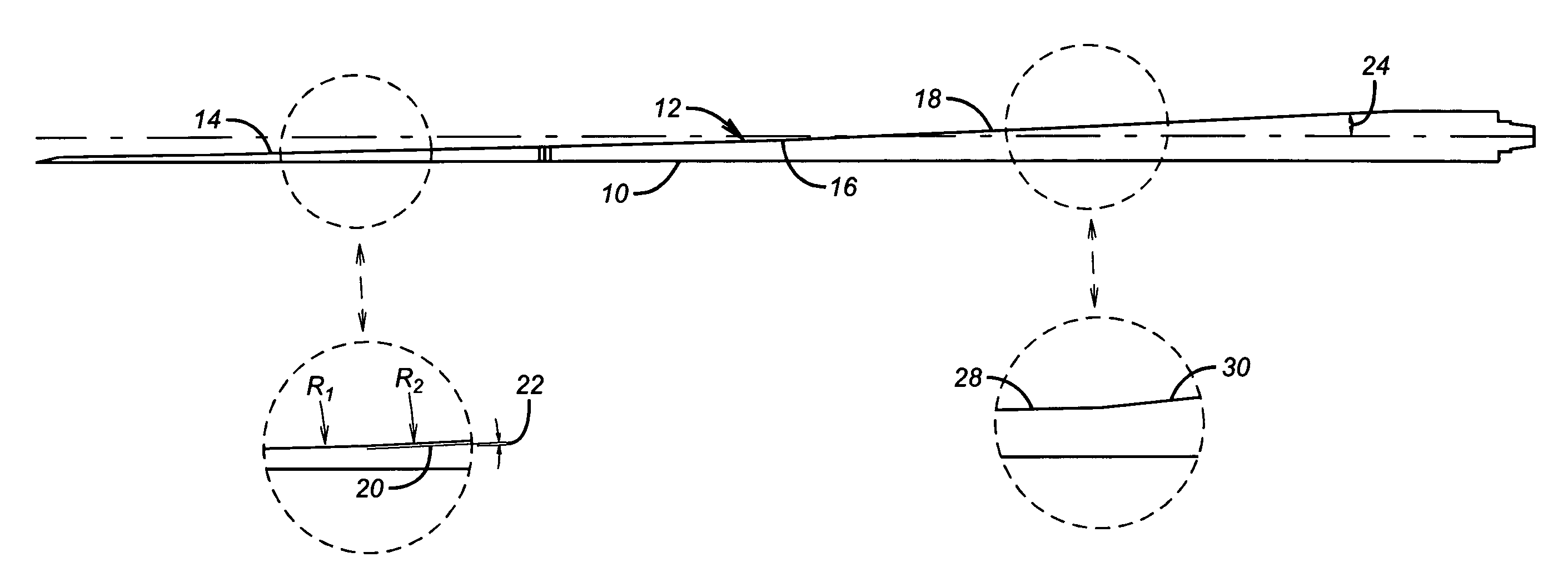
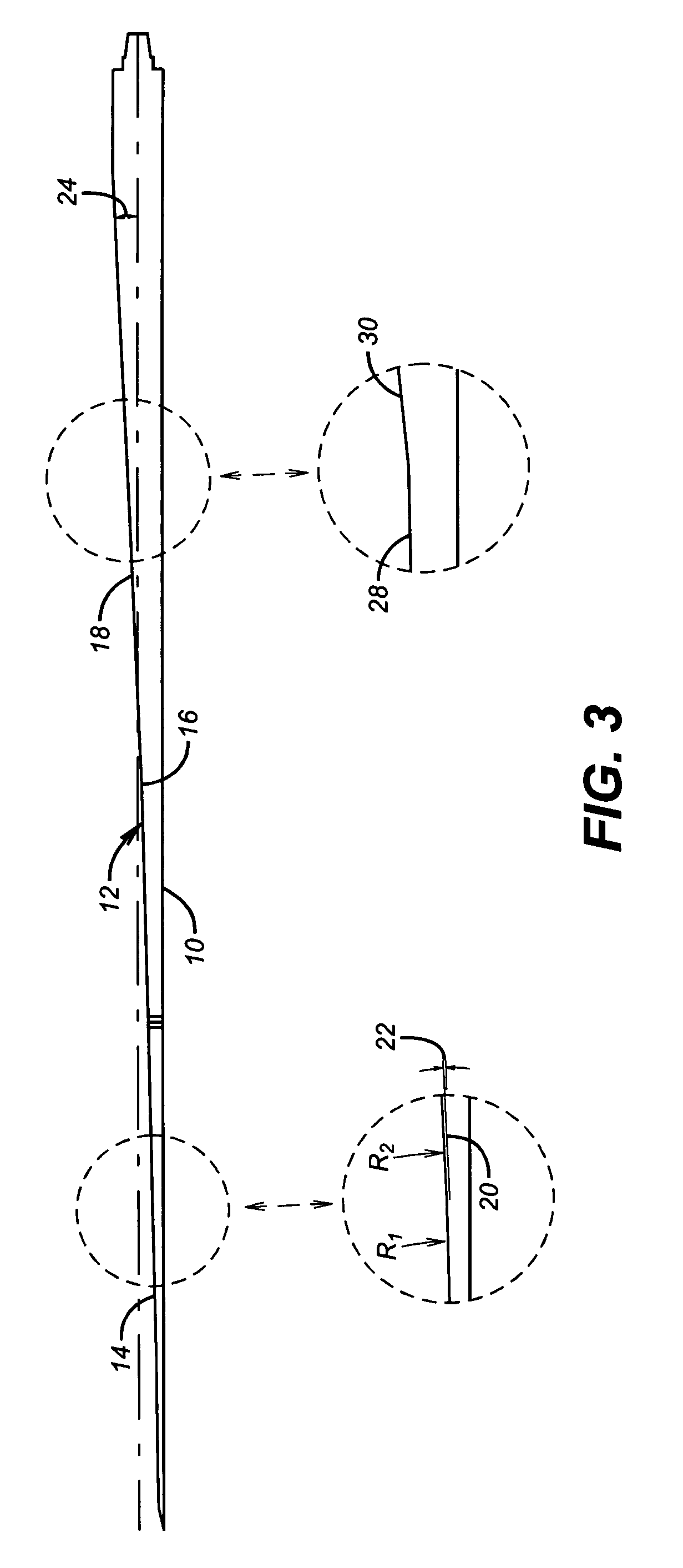
[0015]FIG. 3 shows a whipstock 10 with an overall ramp 12 that has an arcuate upper section 14, a transition point 16 and a lower ramped section 18. The curved section preferably extends for 33% or less of the total length of ramp 12. The ramp 12, for purposes of the percentage allocation, begins below a lug (not shown) that holds a window mill (not shown) to the whipstock 10 for running into the wellbore. While the radius of the curved section can vary with the size of the whipstock 10, the initial portions of the curved section are at a fairly minimal slope so as to exert a fairly moderate lateral force on the window mill as the milling starts. However, unlike totally curved whipstocks of the past, the present invention recognizes that the lateral force must be increased to get the window mill through the window and to properly kick off the lateral. For that reason a transition occurs at 16 to what is preferably a flat surface at a greater incline than the terminal incline at the ...


PUM


Abstract

The whipstock face below the mounting lug is initially curved with a fairly long radius to protect the whipstock body initially. After moving down the minimally sloping curved face a transition to a greater angle is presented to increase the lateral forces on the window mill and to force the mill laterally to exit the tubular through the window. The transition after the curved portion is preferably to a flat inclined surface to the ramp bottom.

Description

FIELD OF THE INVENTION[0001]The field of this invention is whipstock design for making windows in tubulars downhole for the purpose of extending a lateral bore from a main bore.BACKGROUND OF THE INVENTION[0002]Whipstocks are devices that have long been in use to deflect a mill system through casing to create an opening known as a window. Whipstocks tend to be very long so that an inclined face on them can gradually nudge a mill system into the casing wall to start the window and to further guide the milling system until it makes an exit though the window. As a result the window shape is long and thin and narrows at the upper and lower ends. The slope on the whipstock guide surface is generally a small angle or series of angles.[0003]Window milling with whipstocks has several unique issues that can affect the performance of the milling equipment. One concern has been when the center of the mill comes even with the casing wall and there is a tendency for the mill to bog down in that p...

Claims


Application Information

Patent Timeline
Patent Type & Authority Patents(United States)
IPC IPC(8): E21B7/08
CPCE21B7/061
Inventor LEWIS, EVAN G.STOWE, II, CALVIN J.
Owner BAKER HUGHES INC
Why Eureka
Try Eureka