Fixation of a Bone Conduction Floating Mass Transducer

Active Publication Date: 2018-08-30
MED EL ELEKTROMEDIZINISCHE GERAETE GMBH
View PDF5 Cites 6 Cited by
  • Summary
  • Abstract
  • Description
  • Claims
  • Application Information

AI Technical Summary

Benefits of technology

[0009]Embodiments of the present invention are directed to an implantable bone conduction transducer with a center rotational axis radially surrounded by an outer surface, and at least one radial projection projecting radially outward from the outer surface. An implantable transducer receptacle has a receptacle outer surface configured to fit into a receptacle recess in skull bone of a recipient patient, a receptacle inner surface configured to fit around the outer

Problems solved by technology

When the screw holes are not very precise or if the skull bone lacks th

Method used


Image

  • Fixation of a Bone Conduction Floating Mass Transducer
  • Fixation of a Bone Conduction Floating Mass Transducer
  • Fixation of a Bone Conduction Floating Mass Transducer

Examples


Embodiment Construction

[0017]Embodiments of the present invention are directed to arrangements for fixing a bone conduction transducer such as an FMT to an implanted patient's skull bone by directing a lateral clamping force against the bone recess which receives the transducer. Such arrangements avoid the conventional need for bone cement and bone screws and all the related requirements such as a drill template, seats, drill, etc. The depth of the transducer bone bed also can be reduced (e.g., to 2 mm if necessary) without the need for seats so preparing the bone bed is less complicated. In addition, a relatively high lateral clamping force can be applied to the bone so that osseointegration of the transducer site is not mandatory. And, the lateral force approach does not increase the height of the transducer arrangement (as opposed to other approaches such in U.S. Pat. No. 8,241,201).

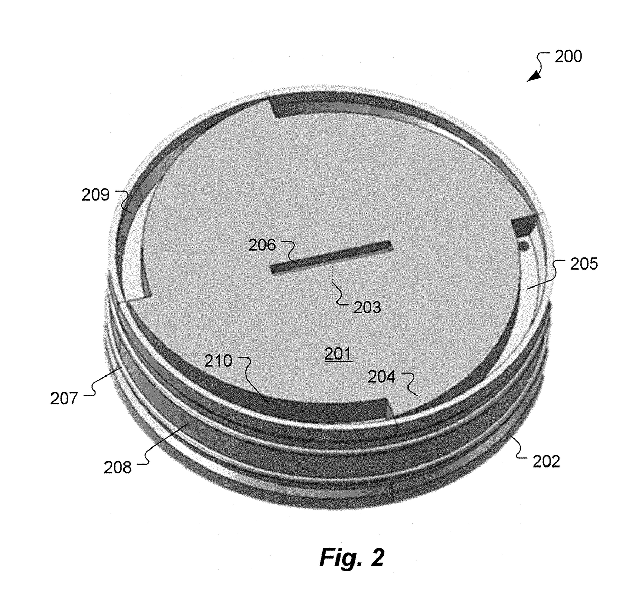
[0018]FIG. 2 shows an elevated perspective top view of an implantable bone conduction transducer arrangement 200 which in...


PUM


Abstract

An implantable bone conduction transducer has a center rotational axis radially surrounded by an outer surface, and at least one radial projection projecting radially outward from the outer surface. An implantable transducer receptacle has a receptacle outer surface configured to fit into a receptacle recess in skull bone of a recipient patient, a receptacle inner surface configured to fit around the outer surface of the transducer, and at least one projection bracket projecting radially inward away from the receptacle inner surface. The at least one projection bracket and the at least one radial projection are configured to cooperate so that rotation of the transducer around the center rotational axis creates increased lateral force between the transducer and the skull bone surrounding the receptacle recess so as to securely engage the transducer with the skull bone.

Description

[0001]This application is a national phase entry of Patent Cooperation Treaty Application PCT / US2016 / 022732, filed Mar. 17, 2016, which in turn claims priority from U.S. Provisional Patent Application 62 / 134,626, filed Mar. 18, 2015, both of which are incorporated herein by reference in their entireties.FIELD OF THE INVENTION[0002]The present invention relates to hearing implants, and more specifically to fixation of a bone conduction floating mass transducer to a patient's skull bone.BACKGROUND ART[0003]A normal ear transmits sounds as shown in FIG. 1 through the outer ear 101 to the tympanic membrane (eardrum) 102, which moves the ossicles of the middle ear 103 (malleus, incus, and stapes) that vibrate the oval window 106 and round window 107 membranes of the cochlea 104. The cochlea 104 is a long narrow duct wound spirally about its axis for approximately two and a half turns. It includes an upper channel known as the scala vestibuli and a lower channel known as the scala tympani...

Claims


Application Information

Patent Timeline
IPC IPC(8): H04R25/00A61F2/28
CPCH04R25/606A61F2/28H04R25/608H04R25/60
Inventor SANTEK, MICHAEL
Owner MED EL ELEKTROMEDIZINISCHE GERAETE GMBH
Why Eureka
Try Eureka