Off-highway dump truck for reducing abrasion and prolonging service life of plate spring
A technology for off-highway and dump trucks, applied in the direction of inclined bearing motion vehicles, springs, leaf springs, etc., can solve the problems of reducing pressure and wear resistance below, and the longest leaf spring is easy to break, so as to improve the service life and impact force. The effect of reducing and extending the life of the leaf spring
- Summary
- Abstract
- Description
- Claims
- Application Information
AI Technical Summary
Problems solved by technology
Method used
Image
Examples
Embodiment 1
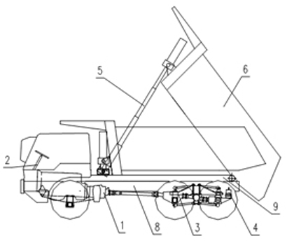
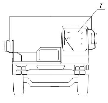
[0066] Example 1 as figure 1 and figure 2 As shown, this kind of non-highway dump truck that reduces wear and improves the service life of the leaf spring includes a car body, a frame, a power system, a transmission system, a car box, tires, and a braking system. Its power system 1 is connected to the On the main frame 8, the steering system 2 is connected to the left front outside of the main frame 8, the suspension system 3 is connected below the main frame 8, the braking system 4 is connected to the inside and outside of the main frame 8, and the lifting system The hydraulic cylinder of 5 is connected to the front end of the subframe 9 and the front plate of the cargo box 6 through the oil cylinder connecting seat, the cargo box 6 is connected to the subframe 9, and the subframe 9 is connected to the main frame through a bracket and a connecting plate 8 above, the cab 7 is connected to the left front of the main frame through brackets. It designs a new type of leaf sprin...
Embodiment 2
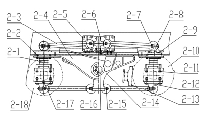
[0083] Embodiment 2 is basically the same as Embodiment 1, and the difference is that its suspension is a balance beam suspension such as diagram 2-1 As shown, there are four rubber main springs 2-1 in total, two of which are connected to the two ends of the equalizing beam 2-4 on the left side of the vehicle frame 2-23 by bolts 2-2, and the other two are connected by bolts 2-2 to the The two ends of the equalizing beam 2-4 on the right side of the vehicle frame 2-23, and the bottom of the four rubber main springs 2-1 are respectively connected to the axle housing processing surfaces of the middle axle 2-18 and the rear axle 2-10 through bolts 2-11 The middle part of the balance beam 2-4 is connected to the two ends of the balance shaft 2-16 with rubber bearing 2-19, rubber bearing cover 2-20, and bolt 2-21, and the balance shaft 2-16 is fixed on the balance shaft support 2-14 Among them, the two balance shaft brackets 2-14 are respectively connected to the vehicle frame 2-23...
Embodiment 3
[0084] Embodiment 3 is basically the same as Embodiment 1, and the difference is that its suspension is another kind of suspension structure such as Figure 3-1 As shown, it is the longitudinal distribution diagram of embodiment 3, the upper thrust rod 3-1 and the lower thrust rod 3-13, the middle bridge 3-14 and the support 3-11, and the four balance beams 3-15 pass through the upper thrust rod beam end The connection of support 3-2, upper thrust rod bridge end support 3-4 and lower thrust rod support 3-9 forms two side-by-side four-bar linkages at the front end and rear end of four balance beams 3-15, which can effectively control Longitudinal runout of middle axle 3-14 and rear axle 3-16. The two ends of the four upper thrust rods 3-1 are respectively connected to the upper thrust rod beam end support 3-2 and the upper thrust rod bridge end support 3-4 by two bolts 3-17, and the upper thrust rod beam end support 3-2 is single The limit is connected on four beams 3-15 and t...
PUM
 Abstract
Description
Claims
Application Information
 - R&D
- Intellectual Property
- Life Sciences
- Materials
- Tech Scout
- Unparalleled Data Quality
- Higher Quality Content
- 60% Fewer Hallucinations
Browse by: Latest US Patents, China's latest patents, Technical Efficacy Thesaurus, Application Domain, Technology Topic, Popular Technical Reports.
© 2025 PatSnap. All rights reserved.Legal|Privacy policy|Modern Slavery Act Transparency Statement|Sitemap|About US| Contact US: help@patsnap.com


