Structure of air-packing device

a technology of air-packing device and structure, which is applied in the direction of packaging, flexible containers, sacks, etc., can solve the problems of expensive mold production, inability to recycle styrofoam, and inability to produce mold, so as to effectively damp the shock to the product therein, and prevent the effect of reverse flow of air

Inactive Publication Date: 2008-09-09
AIR PAQ
View PDF8 Cites 30 Cited by
  • Summary
  • Abstract
  • Description
  • Claims
  • Application Information

AI Technical Summary

Benefits of technology

[0009]It is, therefore, an object of the present invention to provide a structure of an air-packing device for packing a product that can minimize a mechanical shock or vibration to the product.
[0010]It is another object of the present invention to provide a structure of a check valve for the air-packing device that can reliably prevent reverse flow of the air in the air containers of the air-packing device.
[0018]According to the present invention, the air-packing device can minimize shocks or vibrations to the product when the product is dropped or collided. The sheet form of the air-packing device is folded and the heat-seal treatment is applied thereto, thereby creating a structure unique to a production to be protected. The air-packing device is basically configured by the wall portion and the pocket portion. The wall portion is comprised of multiple rows of air containers. The pocket portion is formed at about the center of the wall portion. Consequently, even when a large shock or vibration is applied to the air-packing device, the pocket portion will not touch the ground. Further, since the pocket portion is flexibly moved when the shock is applied, it can effectively damp the shock to the product therein. The check valves in the air-packing device have a unique structure for preventing reverse flows of the air. The air-packing device of the present invention has a relatively simple structure with reliable check valves, thus, the present invention is able to provide a reliable air-packing device with low cost.

Problems solved by technology

For example, recycling the styrofoam is not possible, soot is produced when it burns, a flake or chip comes off when it is snagged because of its brittleness, and expensive mold is needed for its production, and a relatively large warehouse is necessary for storage.
Third, the air-packing device does not produce a chip or dust which may have adverse effects on precision products.

Method used


Image

  • Structure of air-packing device
  • Structure of air-packing device
  • Structure of air-packing device

Examples


Embodiment Construction

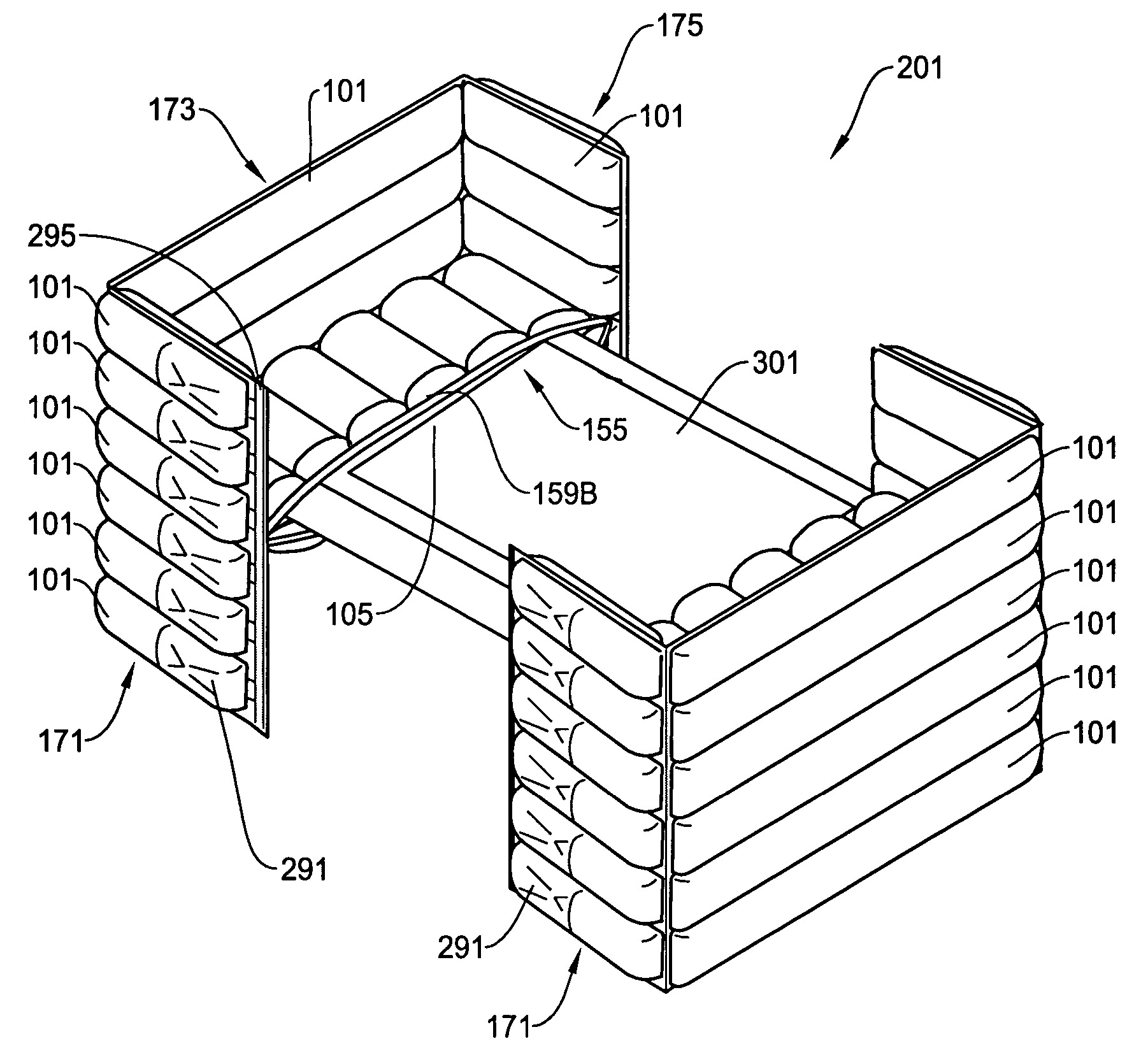
[0034]The air-packing device of the present invention will be described in detail with reference to the accompanying drawings. It should be noted that while the present invention is described where compressed air is used to inflate the air-packing device for an illustration purpose, other fluids such as other types of gas or liquid may also be used. The air-packing device is typically used in a container box to pack a product during the distribution of the product.

[0035]The air-packing device of the present invention is advantageous in protecting products that are sensitive to shock or vibration such as hard disc drivers, personal computers, DVD drivers, etc. Other examples of such products include, but not limited to, glassware, ceramic ware, musical instruments, paintings, antiques, etc. The air-packing device of the present invention is especially suited to products that require protection but are sensitive at certain locations. For example, an LCD (liquid crystal display) is mor...


PUM


Abstract

An air-packing device has an improved shock absorbing capability to protect a product in a container box. The air-packing device is comprised of a plurality of edge air-packing blocks. Each edge air-packing device includes a wall portion that surrounds and supports a pocket portion that holds an edge of the product to be protected such that the pocket portion does not contact the ground when shocks are applied to the air-packing device. Each of the enclosure portion and the pocket portion is configured by first and second thermoplastic films which are bonded at predetermined portions thereby creating a plurality of air containers. Each of the air containers has a check valve for allowing the compressed air to flow only in a forward direction.

Description

FIELD OF THE INVENTION[0001]This invention relates to a structure of an air-packing device for use as packing material, and more particularly, to a structure of an air-packing device and check valves incorporated therein for achieving an improved shock absorbing capability to protect a product from shock or impact where the air-packing device is configured by a plurality of edge or corner air-packing blocks each having a pocket so that a product inserted in the pocket portions is packed and suspended by the edge or corner air-packing blocks with an ample clearance from the ground.BACKGROUND OF THE INVENTION[0002]There are several choices as shock absorbing material used for protecting products from damages due to physical shocks applied to the products from mishandling or stacking. One of those choices is styrofoam. Although using styrofoam as packaging material has benefits such as good thermal insulation and light weight, it also has various disadvantages. For example, recycling t...

Claims


Application Information

Patent Timeline
Patent Type & Authority Patents(United States)
IPC IPC(8): B65D81/02
CPCB65D81/052
Inventor YOSHIFUSA, KARK K.
Owner AIR PAQ
Why Eureka
Try Eureka