Electrical connector having improved shield

a technology of shielding and electrical connectors, which is applied in the direction of two-part coupling devices, coupling device connections, printed circuits, etc., can solve the problem that the outer shield described above cannot be fastened to the inner shield firmly

Inactive Publication Date: 2008-09-09
HON HAI PRECISION IND CO LTD
View PDF90 Cites 17 Cited by
  • Summary
  • Abstract
  • Description
  • Claims
  • Application Information

AI Technical Summary

Benefits of technology

[0010]Advantages of the present invention are to provide a lower shield formed with a pair of improved side walls, each having a pair of projecting portions engaging with the corresponding protrusion disposed on the upper shield for fastening the upper shield to the lower shield tightly.

Problems solved by technology

However, the outer shield described above could not fasten the inner shield firmly.

Method used


Image

  • Electrical connector having improved shield
  • Electrical connector having improved shield
  • Electrical connector having improved shield

Examples


Embodiment Construction

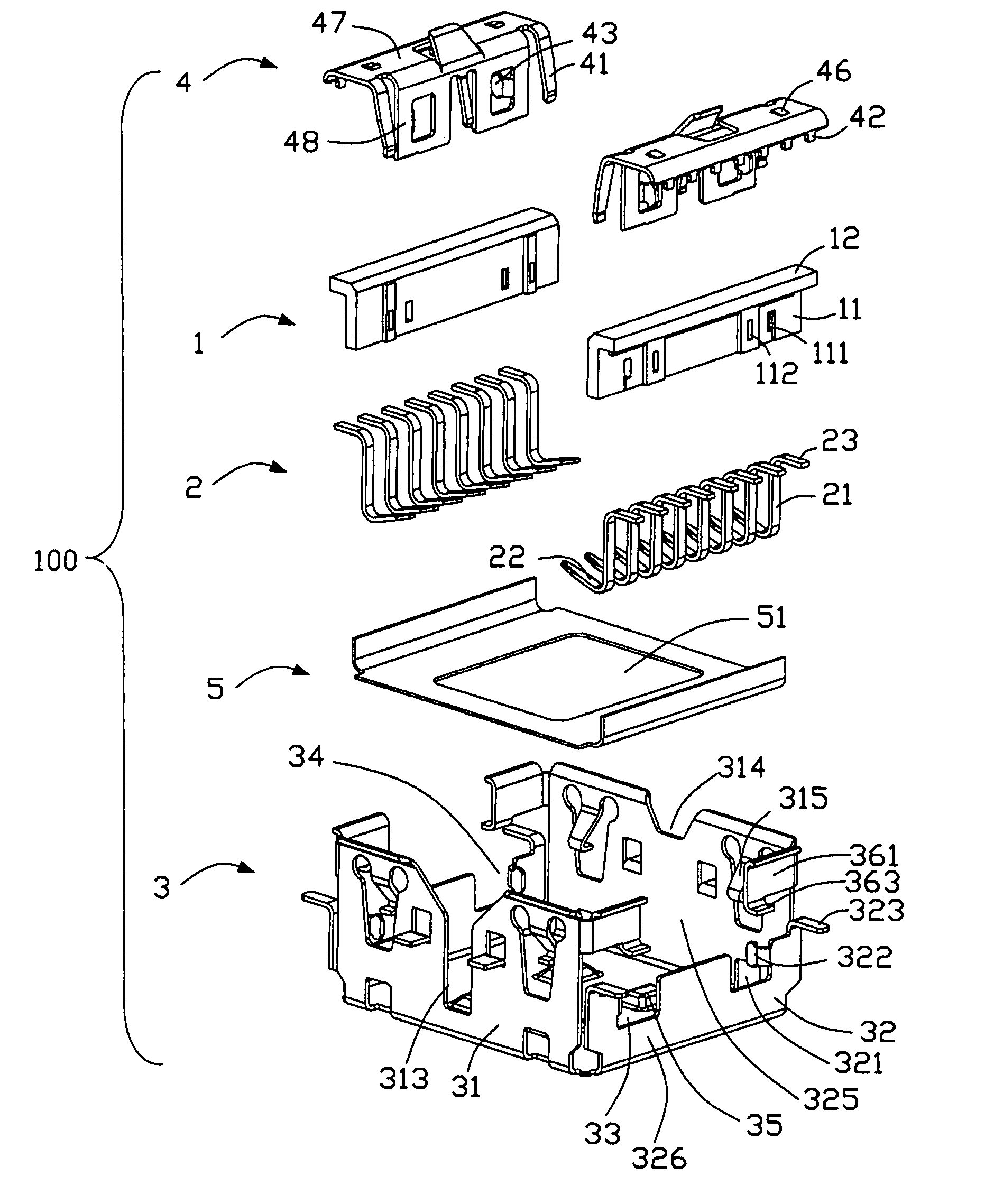
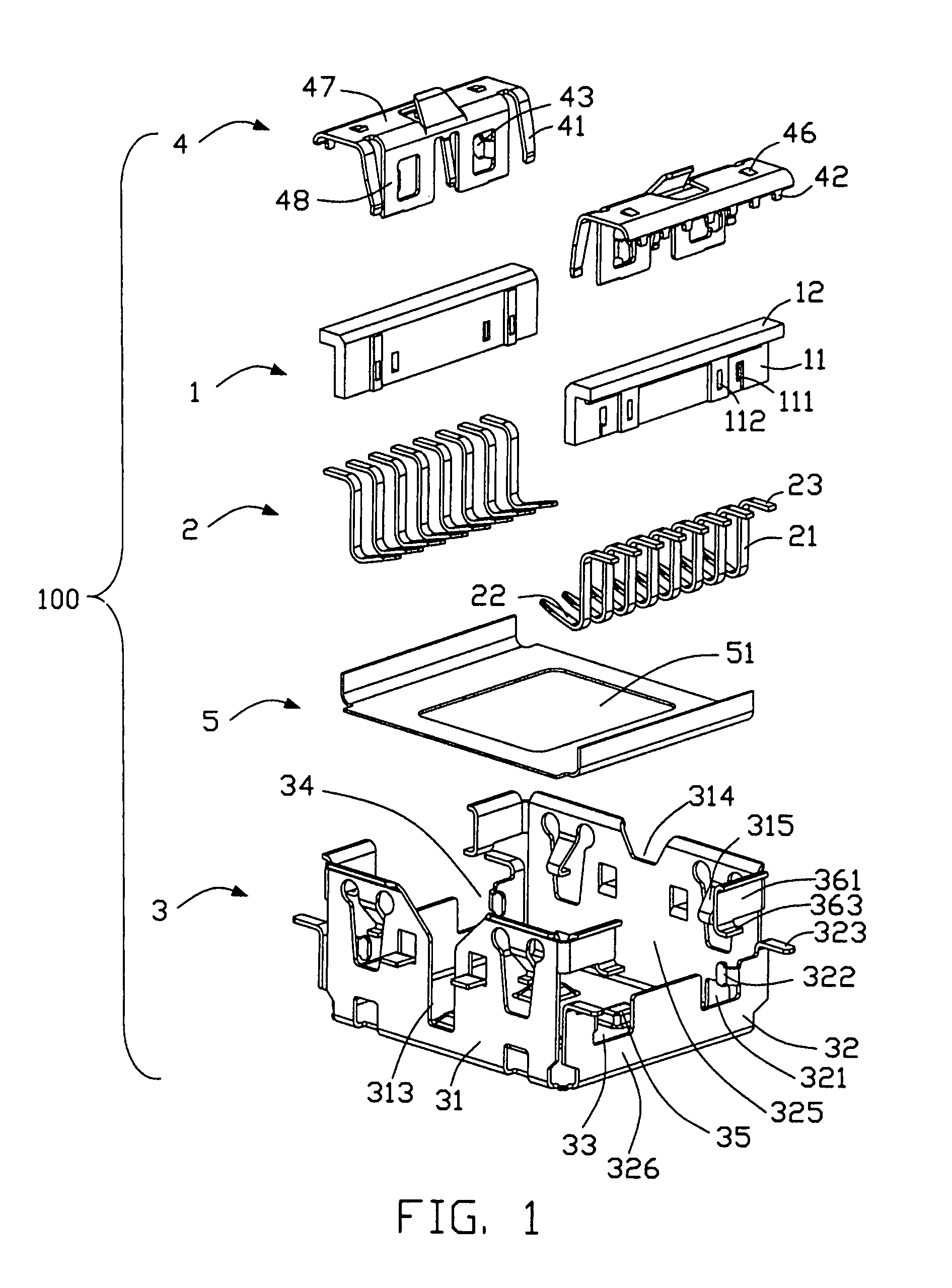
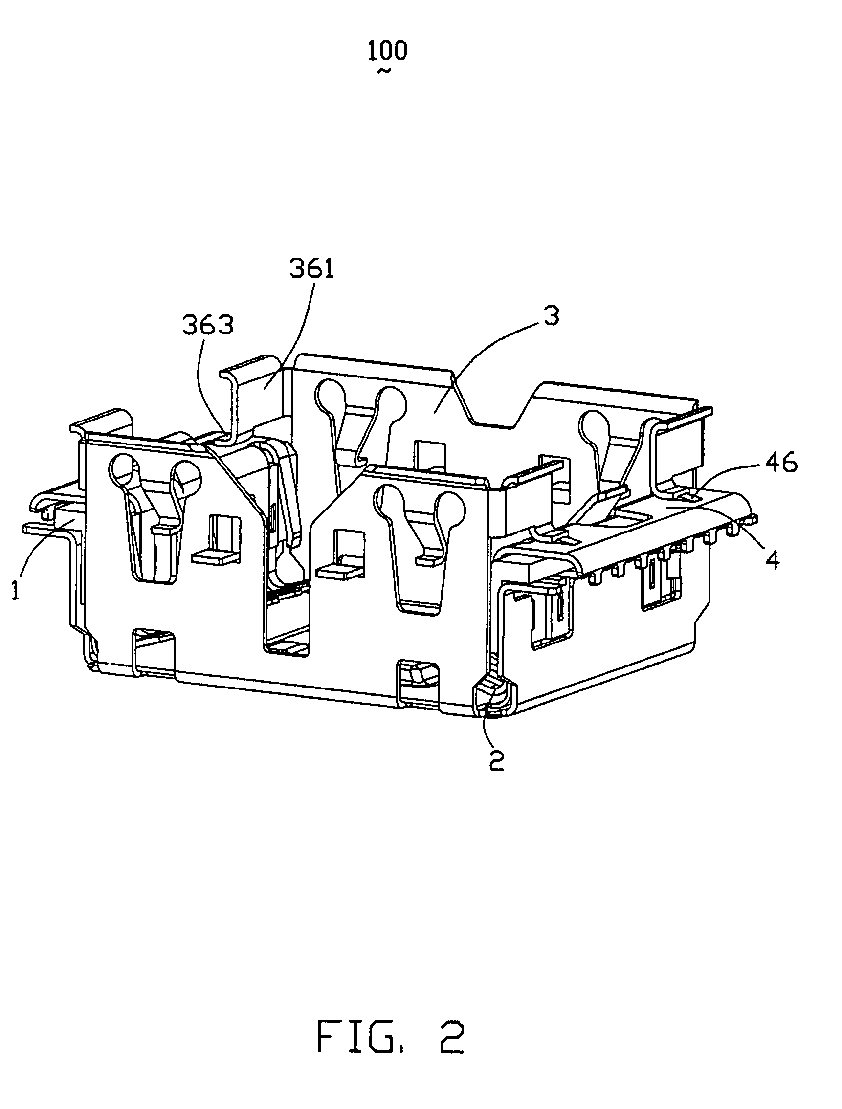
[0014]Reference will now be made to the drawing figures to describe the present invention in detail. Referring to FIGS. 1-2, an electrical connector 100 in accordance with the present invention is adapted for electrically connecting an electrical element (not shown) to a printed circuit board (not shown). The electrical connector 100 comprises a pair of insulative housings 1, a plurality of terminals 2 fixed to the insulative housing 1 by insert molding, a pair of upper shields 4 attached to the insulative housing 1 and a lower shield 3 for receiving the insulative housing 1.

[0015]The insulative housing 1 includes a main portion 11 and a bending portion 12 extending laterally from an upper edge of the main portion 11. The main portion 11 is provided with a locking hole 111 for locking with the lower shield 3 and a retention hole 112 for engaging with the upper shield 4.

[0016]The terminals 2 are configured in a “Z”-shape. Each terminal 2 comprises a vertical intermediate portion 21 m...


PUM


Abstract

An electrical connector (100) includes a lower shield (3), an insulative housing (1) assembled to the lower shield, a number of terminals (2) and a pair of upper shields (4). The lower shield has a bottom wall (33) and a pair of first side walls (32). Each first side wall has a pair of upper base portions (361) and a lower base portion (326) and defines a recess (325) between the upper base portions and the lower base portion. Each upper base portion has a projecting portion (363) extending outwardly therefrom through the recess for engaging with a protrusion (46) disposed on a top surface of the upper shield.

Description

BACKGROUND OF THE INVENTION[0001]1. Field of the Invention[0002]The present invention relates to a shielded electrical connector, and particularly to a shielded electrical connector in which an electrical element is fitted.[0003]2. Description of Prior Arts[0004]With development of miniature and multifunctional electronic devices, consumer electronics such as cell phone, Personal Digital Assistant etc., are designed to provide a camera module in virtue of an electrical connector. Generally, a shield member is assembled to the electrical connector to reduce EMI (electromagnetic interference).[0005]U.S. Patent Application Publication No. 2006 / 0216996 published on Sep. 28, 2006, discloses a connector for receiving an electrical element, including an outer shield mounted to a printed circuit board, an insulative housing attached to the outer shield, a plurality of contacts fixed to the insulative housing, and an inner shell attached to the insulative housing. The inner shell has a pair ...

Claims


Application Information

Patent Timeline
Patent Type & Authority Patents(United States)
IPC IPC(8): H01R13/648
CPCH01R23/6873H01R13/506H01R13/6582H01R13/6594H01R12/00
Inventor WANG, LONG-FEI
Owner HON HAI PRECISION IND CO LTD
Why Eureka
Try Eureka