Lens machining machine

a technology for machining machines and lenses, applied in the direction of optical surface grinding machines, manufacturing tools, transportation and packaging, etc., can solve the problems of limited polishing or machining force on the one hand, and high cost of robot or robot arms used in this field

Active Publication Date: 2008-09-09
SCHNEIDER GMBH & CO KG
View PDF12 Cites 16 Cited by
  • Summary
  • Abstract
  • Description
  • Claims
  • Application Information

AI Technical Summary

Benefits of technology

[0005]In this way, by utilizing the aforesaid axes in conjunction with available drive units for the axes, such as circulating ball spindle drives, one achieves on the one hand the requisite diversity of motion of the workpiece drives and on the other hand the desired machining force for the workpiece drives. In addition, a simple parallel use of a second workpiece drive is possible, so that the processing time for a pair of lenses is roughly in the range of the processing time for one lens using a robot arm. It should be noted that lenses are basically manufactured in pairs, so that thanks to the use of two workpiece drives and two machining stations one substantially simplifies the logistics, i.e., the bringing up and carrying away of the lenses, as well as the machining cycle for the lenses. The two workpiece drives each have a spindle rotation axis c1, c2, thereby providing a guided rotation of the workpieces. The respective spindle or the respective workpiece drive can be swiveled about the first swivel axis b1, b2 in a pendulum motion. This pendulum motion is provided by a swivel motor. The swivel motor is arranged together with the respective workpiece drive on a translation carriage, able to move in translation. The translation carriage moves in the direction of the axis of translation and is separately actuated and driven for each workpiece drive and each swivel motor. The two workpiece drives thus constructed, including the swivel motors and the translatory carriages, are together arranged on a swivel unit configured as a swivel plate and are swiveled via this swivel plate about the turning axis k and optionally lifted or lowered in a direction parallel to a lifting axis w. Preferably, the position and the orientation of the lifting axis w and the turning axis k. The swivel motion about the turning axis k serves for the horizontal positioning of the two workpiece drives in the region of a machining station, on the one hand, and in the region of a workpiece changer or workpiece stock, or a washing station, on the other hand. The lifting and lowering motion in the direction of the lifting axis w serves for a vertical positioning in the region of the washing station or the workpiece changer and in the region of the machining station.
[0023]In addition, it is beneficial that the tool magazine is removed from the machining machine and kept in liquid on the outside, and the tool magazine is installed and secured in the machine with regard to its relative position. This enables a shutting off of the machine at any given time, without danger of the tools drying out.

Problems solved by technology

The robot or robot arm used here is on the one hand very costly and on the other hand affords a limited polishing or machining force, depending on its radius of action.

Method used


Image

  • Lens machining machine
  • Lens machining machine
  • Lens machining machine

Examples


Embodiment Construction

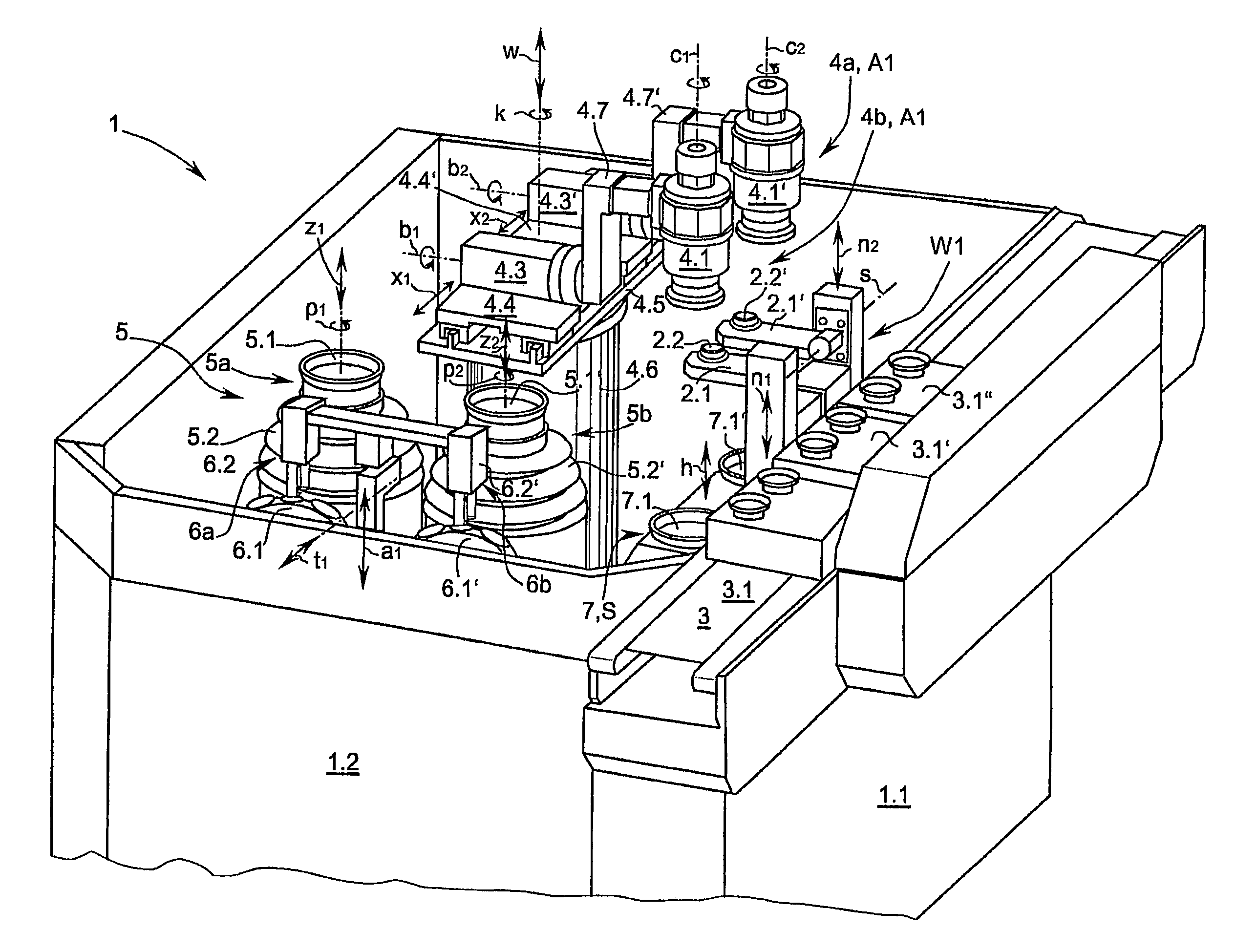
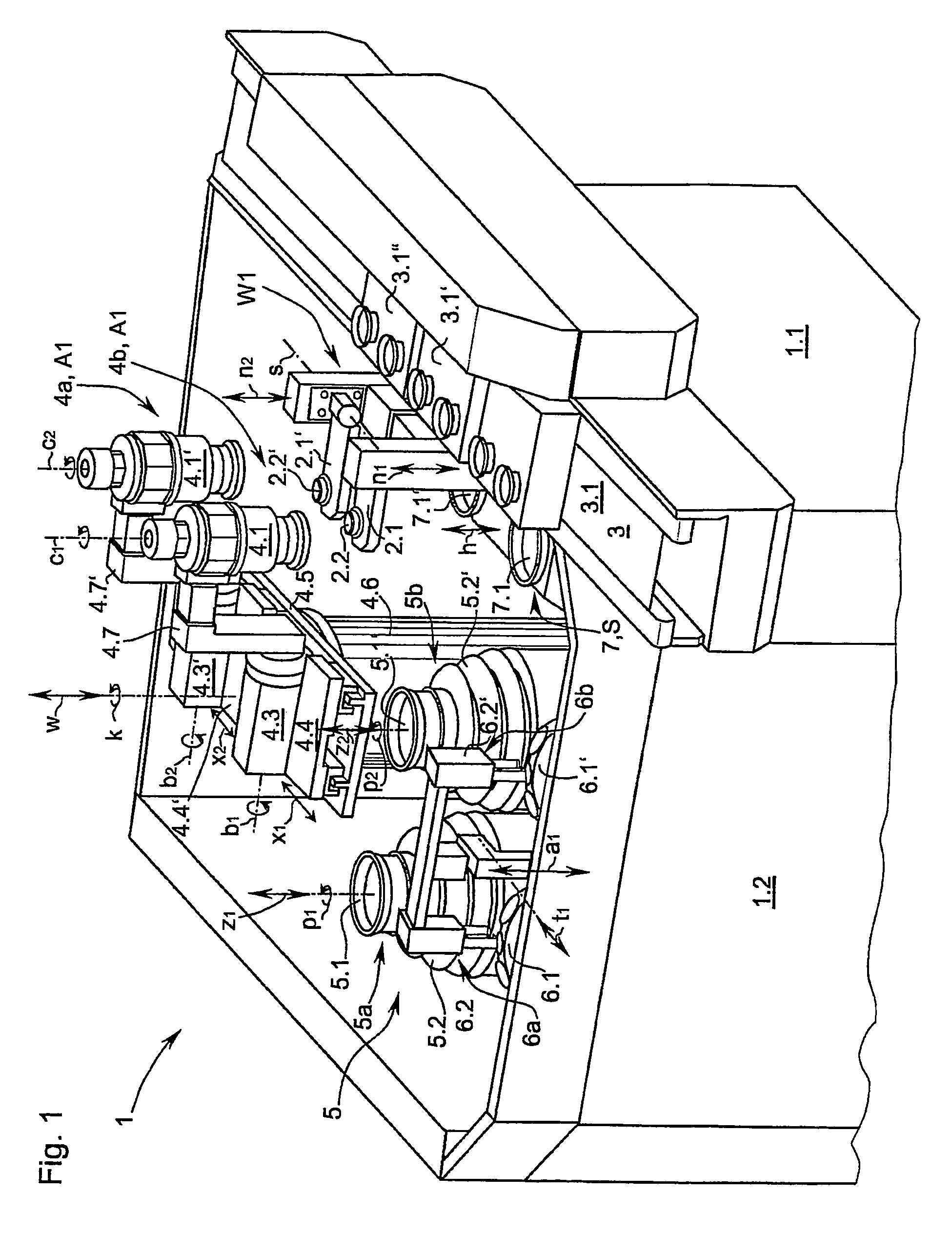
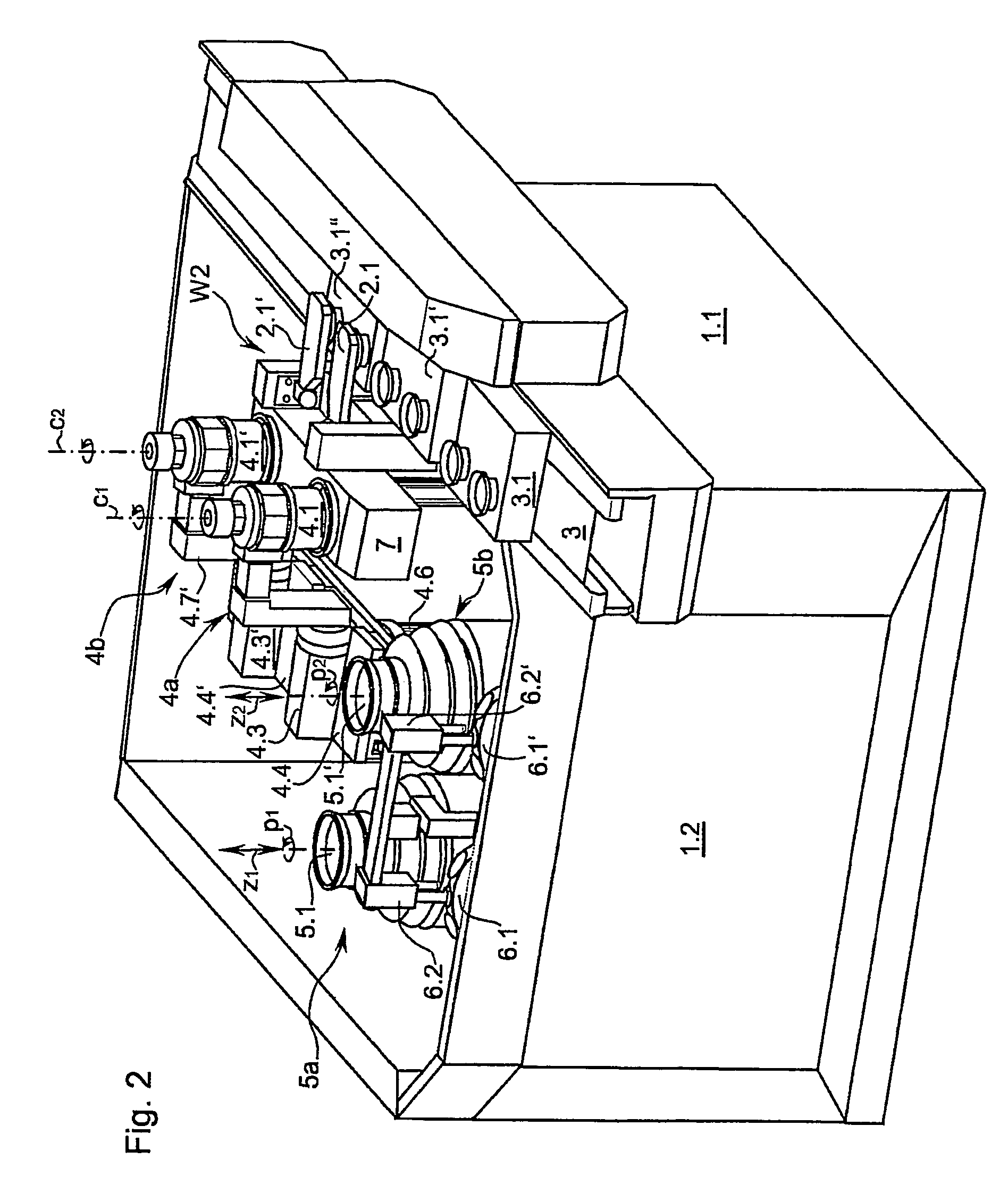
[0028]A machining machine as represented in FIG. 1 and configured as a polishing machine 1 has a conveyor belt 3 for optical lenses or workpiece boxes 3.1-3.1″, by which the transport boxes 3.1-3.1″ are delivered to a pair of workpiece changers 2.1, 2.1′ of the polishing machine 1. The respective workpiece changer 2.1, 2.1′ is configured as a swivel arm, which can swivel 180° about a swivel axis s. At the free end of the respective swivel arm 2.1, 2.1′ there is provided a suction cup 2.2, 2.2′ to receive a workpiece, or lens. The suction cup 2.2, 2.2′ is connected via pneumatic lines (not shown) to a low pressure receiver or pump (not shown). In order to pick up the lenses or pass the lenses on, the workpiece changer 2.1, 2.1′ furthermore has a linear guide able to travel in the direction of a respective lowering axis n1, n2, not further represented, by which the two swivel arms 2.1, 2.1′ can move essentially in the vertical direction, perpendicular to the swivel axis s. To pick up ...


PUM

PropertyMeasurementUnit
of rotationaaaaaaaaaa
angleaaaaaaaaaa
axis of rotationaaaaaaaaaa

Abstract

The invention relates to a machining machine for lenses, which comprises a first workpiece drive, configured as the transport receptacle and having a workpiece spindle, a workpiece changer for exchanging workpieces between the workpiece drive and a workpiece stock, and a machining station for machining a workpiece. The workpiece spindle of the workpiece drive can be rotated about an axis of rotation (c1). The workpiece drive can be swiveled about a first swiveling axis (b1) which is arranged at a right angle to the axis of rotation (c1). The work piece drive can be rotated about an axis of rotation (k) which is arranged at a right angle to the first swiveling axis (b1). The machining machine according to the invention is characterized in that at least one further workpiece drive is provided and has a spindle that can be rotated about a respective axis of rotation (c1, c2). Both workpiece drives can be swiveled about a first swiveling axis (b1, b2) which is arranged at a right angle to the respective axis of rotation (c1, c2). Both workpiece drives can be displaced and driven in a translatory manner about a translatory axis of displacement (x1, x2) which is arranged at a right angle to the first swiveling axis (b1, b2). Both workpiece drives can be rotated together about the axis of rotation (k).

Description

FIELD OF INVENTION[0001]The invention pertains to a machining machine for lenses according to the claims, as well as a method for operating the machining machine. At issue is a machining machine for optical lenses with a first workpiece drive configured as a transport receptacle with a workpiece spindle having a chuck, a workpiece changer configured as a workpiece turnover for exchanging workpieces between the workpiece drive and a workpiece stock, and a machining station for machining a workpiece, wherein the workpiece spindle of the workpiece drive can rotate about an axis of rotation c1 and the workpiece drive can swivel about a first swivel axis b1, arranged at right angle to the axis of rotation c1, and the workpiece drive can turn about a turning axis k arranged at right angles to the first swivel axis b1.BACKGROUND OF THE INVENTION[0002]A lens machining machine is already known from DE 102 48 104 A1. This lens machining machine has a table with at least two work or tool stati...

Claims


Application Information

Patent Timeline
Patent Type & Authority Patents(United States)
IPC IPC(8): B24B49/00B24B13/00B24B27/00
CPCB24B27/0061B24B13/0031
Inventor SCHNEIDER, GUNTERBUCHENAUER, HELWIGKRAMER, KLAUS
Owner SCHNEIDER GMBH & CO KG
Why Eureka
Try Eureka