
Real-time preview for panoramic images

a real-time preview and panoramic technology, applied in the field of panoramic image construction, can solve the problems of not knowing for sure that the scene has been covered sufficiently, the overlap of images is known, and users are unable to see the “big picture” easily

Active Publication Date: 2008-09-09
ZHIGU HLDG
View PDF16 Cites 294 Cited by
  • Summary
  • Abstract
  • Description
  • Claims
  • Application Information

AI Technical Summary

Benefits of technology

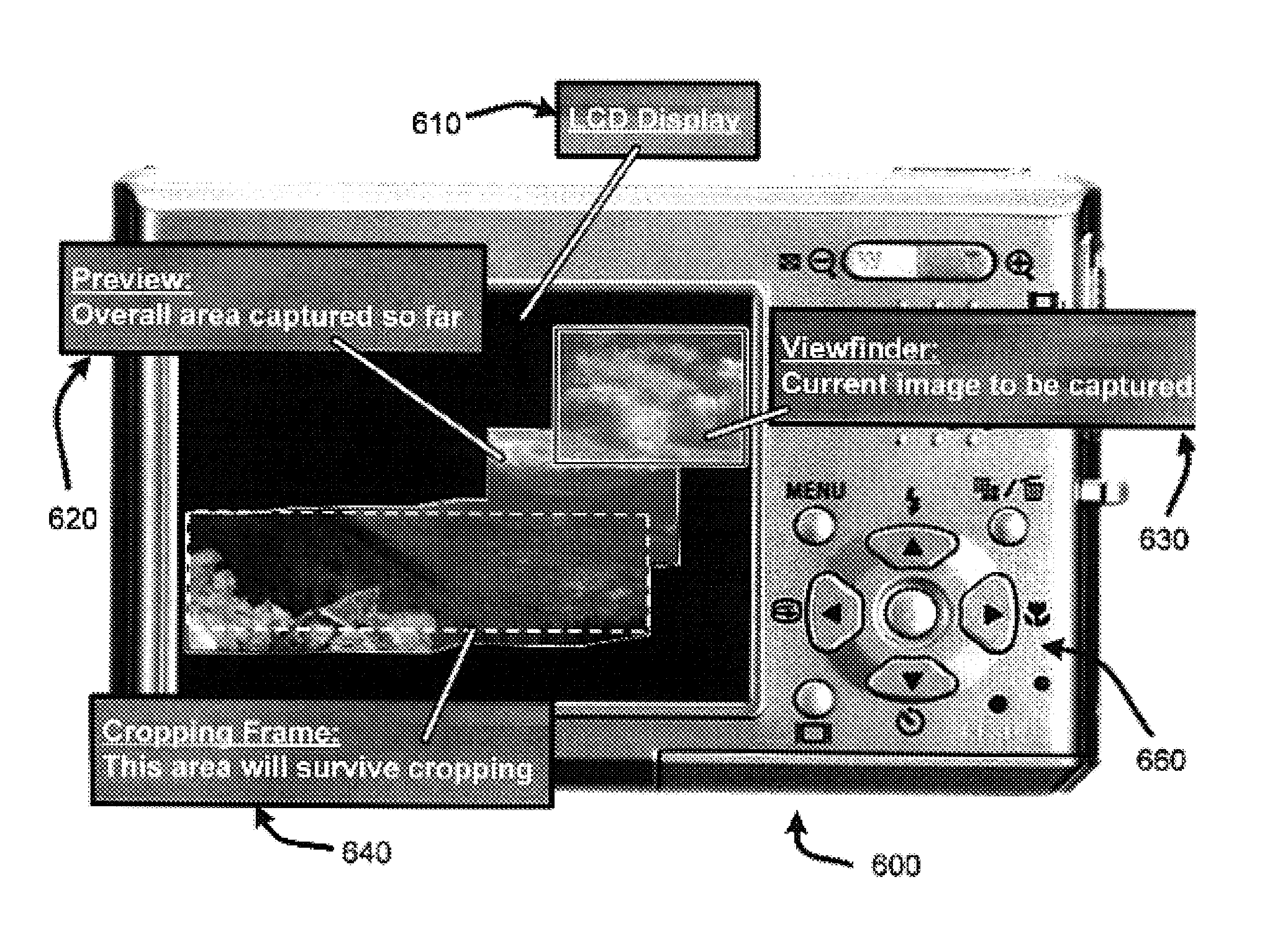
"The patent describes a device called the Panoramic Viewfinder, which helps users capture images for creating panoramic mosaic images. The device includes an interactive viewfinder display that provides users with real-time assistance in capturing images. It allows users to \"brush\" a panoramic image of a scene while shooting the images. The device also includes a mosaic preview that shows the full extent of the mosaic image that can be constructed from the captured images. The mosaic preview can be scaled, panned, or zoomed to help users direct the camera to uncovered areas of the desired panorama. The device also includes a live display window that represents the content of the camera viewfinder, which helps users see where the next image will fit into the existing mosaic. The device provides a unique system and method for using a digital camera to generate mosaiced panoramic images of a scene."

Problems solved by technology

Early stitching schemes generally required a carefully controlled camera motion resulting in a known overlap between images.
However, one problem with such post processing of images is that the user never really knows for sure that sufficient coverage of the scene has been achieved to ensure that the desired panorama can be constructed from the set of captured image frames until the panorama has actually been generated at some later time.
As a consequence it can be hard for users to see “the big picture.”
In particular, using conventional image stitching schemes, it is not until the images are uploaded from the camera to the computing device (such as a PC-type computer, or the like) that users find that the resulting panorama is flawed.
For example, gaps will occur in the panorama if users miss one or more spots.
Gaps will also occur if the stitching program is unable to insert one or more of the captured images into the panorama, e.g., due to too little overlap between pictures, due to a lack of texture, due to problems with image focus (image too blurry), etc.
Further, while gaps at the edge of a panorama can be removed by cropping the panorama, this may cause other desired image elements to be lost outside the cropping boundaries.
Another problem with conventional post-processing approaches involves the issue of “ghosting” where objects have moved from one frame to the next while the images for the panorama were being taken.
Unfortunately, by the time users notice such flaws, it is typically too late to retake the missing or flawed image frames.
This redundancy-based approach, however, is costly is terms of time and especially in terms of storage space (as more pictures are taken) and it still cannot guarantee successful generation of the resulting panoramic images.
However, the VideoBrush™ system supports only translational motion, not full-view panoramas.
Further, another problem with systems such as that offered by VideoBrush™ is that they do not provide explicit indications for issues such as whether desired scene elements will survive cropping to a conventional rectangular format, or whether the resulting panorama will be subject to ghosting.
Unfortunately, the approach offered by such cameras is limited in several ways.
First, such approaches do not extend well to 2D panoramas.
In particular, even if users could choose a connection direction between images as they move along, shooting a large 2D image by brushing back and forth in rows would only guarantee connectivity between predecessor and successor images, but not between the rows themselves.
Second, such approaches offer no guarantee that the desired scene elements will survive cropping.
Third, such approaches tend to limit the users' freedom, as the user is required to constantly focus on the LCD display of the camera.
Further, issues such as ghosting and focus are not adequately addressed by such systems.
Unfortunately, fixing such flaws still requires the user to retake the entire panorama, as images can not be inserted into the existing panorama to fix any identified flaws.

Method used


Image

  • Real-time preview for panoramic images
  • Real-time preview for panoramic images
  • Real-time preview for panoramic images

Examples


Embodiment Construction

[0037]In the following description of the preferred embodiments of the present invention, reference is made to the accompanying drawings, which form a part hereof, and in which is shown by way of illustration specific embodiments in which the invention may be practiced. It is understood that other embodiments may be utilized and structural changes may be made without departing from the scope of the present invention.

1.0 Exemplary Operating Environments:

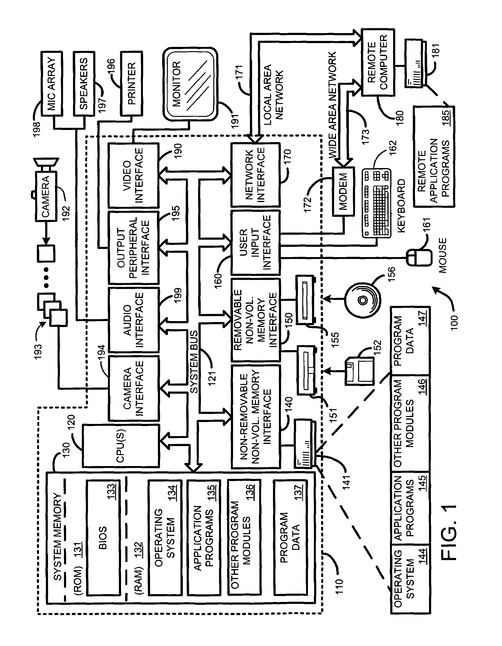
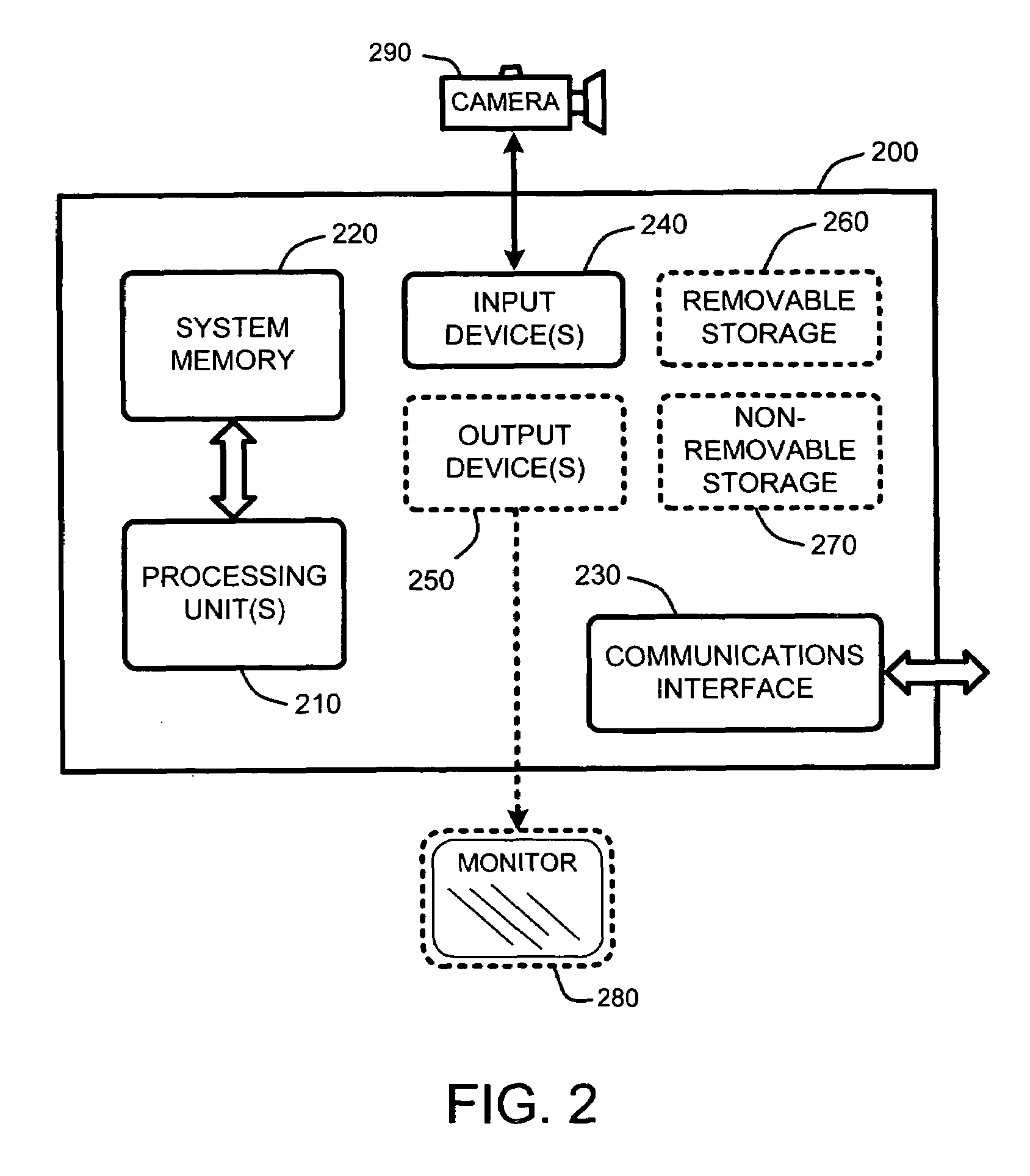
[0038]FIG. 1, FIG. 2, and FIG. 3 illustrate various examples of suitable computing environments on which various embodiments and elements of a “Panoramic Viewfinder,” as described herein, may be implemented.

[0039]For example, FIG. 1 illustrates an example of a general computing system environment 100. The computing system environment 100 is only one example of a suitable computing environment and is not intended to suggest any limitation as to the scope of use or functionality of the invention. Neither should the computing environment...


PUM


Abstract

A “Panoramic Viewfinder” provides an intuitive interactive viewfinder display which operates on a digital camera display screen. This interactive viewfinder provides real-time assistance in capturing images for constructing panoramic image mosaics. The Panoramic Viewfinder “brushes” a panorama from images captured in any order, while providing visual feedback to the user for ensuring that desired scene elements will appear in the final panorama. This visual feedback presents real-time stitched previews of the panorama while capturing images. In one embodiment, the viewfinder display of the Panoramic Viewfinder includes a “mosaic preview” which presents a stitched mosaic preview of the captured images; a live display window representing a “current content” of the camera viewfinder, which is mapped to a matching location within the mosaic preview; and an optional panoramic “cropping frame” overlaid onto the mosaic preview which illustrates a section of the mosaic which will survive a rectangular cropping of the mosaic.

Description

BACKGROUND[0001]1. Technical Field[0002]The invention is related to construction of panoramic images, and in particular, to an image capture device, such as a digital still or video camera, which provides real-time interactive assistance to a user in capturing images used in constructing the panoramic images.[0003]2. Related Art[0004]In general, a mosaic panoramic image is an image that has been expanded in one or more dimensions by combining multiple overlapping image frames to generate the panorama. As a result, the panoramic image is typically larger than the size that a conventional image capture device (such as a digital still or video camera) is capable of capturing in a single image frame.[0005]A number of conventional techniques have been developed to generate such panoramic images. For example, the basic approach is to simply take a plurality of regular photographic or video images in order to cover the entirety of the desired viewing space. These images are then aligned an...

Claims


Application Information

Patent Timeline
Patent Type & Authority Patents(United States)
IPC IPC(8): G03B41/00G03B13/02H04N5/222
CPCG03B13/02G03B17/18H04N5/262H04N5/23293H04N5/23238H04N23/698H04N23/634
Inventor BAUDISCH, PATRICKPAL, CHRISRUDOLPH, ERICSTEEDLY, DREWSZELISKI, RICHARDTAN, DESNEYUYTTENDAELE, MATTHEW
Owner ZHIGU HLDG
Learn More