Eureka AIR delivers breakthrough ideas for toughest innovation challenges, trusted by R&D personnel around the world.

Coiling device and method for rolled or drawn long products

a technology of coiling device and long product, which is applied in the field of coiling device, can solve the problems of removing the finished coil from the mandrel, the whole longitudinal extension of the coil, and the operation of the coil to form,

Inactive Publication Date: 2008-09-16
DANIELI & C OFF MEC SPA
View PDF20 Cites 1 Cited by
  • Summary
  • Abstract
  • Description
  • Claims
  • Application Information

AI Technical Summary

Benefits of technology

[0015]It is also a purpose of the invention to simplify maintenance operations on said device.
[0016]The advantages achieved give a coil having a desired geometric profile which allows to exploit the storage space, also in height, to optimize the handling and transport steps, and gives a better functioning to the user machines, which can thus work at greater speed.

Problems solved by technology

It is known that the operation to form the coil, so that the spirals are compact and uniformly distributed in every layer and for the whole longitudinal extension of the coil, is very delicate.
The problem of easily removing the finished coils from the mandrel is also known.
If the operation to remove the coil is not carried out correctly, defects may occur in the finished coils, such as for example the wound spirals may be released and / or the coiled roll may have a bad aesthetic appearance.
Moreover, if the coil does not have a regular geometry, there are problems of stacking during the storage step, and also problems with installing the coil on the machine which uses the same, and problems with the correct unwinding of the coiled product.

Method used


Image

  • Coiling device and method for rolled or drawn long products
  • Coiling device and method for rolled or drawn long products
  • Coiling device and method for rolled or drawn long products

Examples


Embodiment Construction

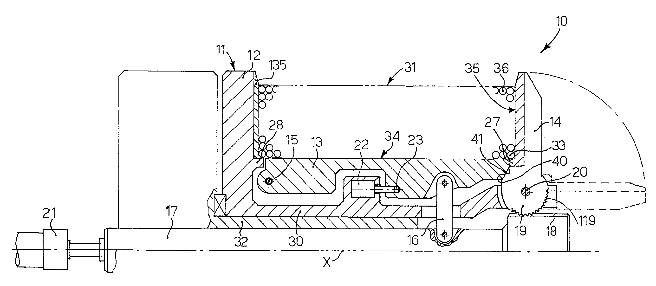
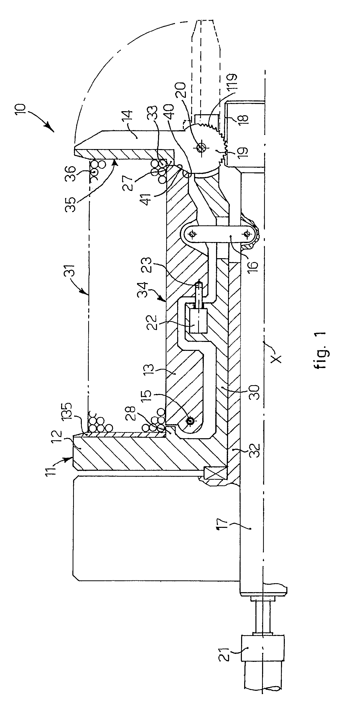
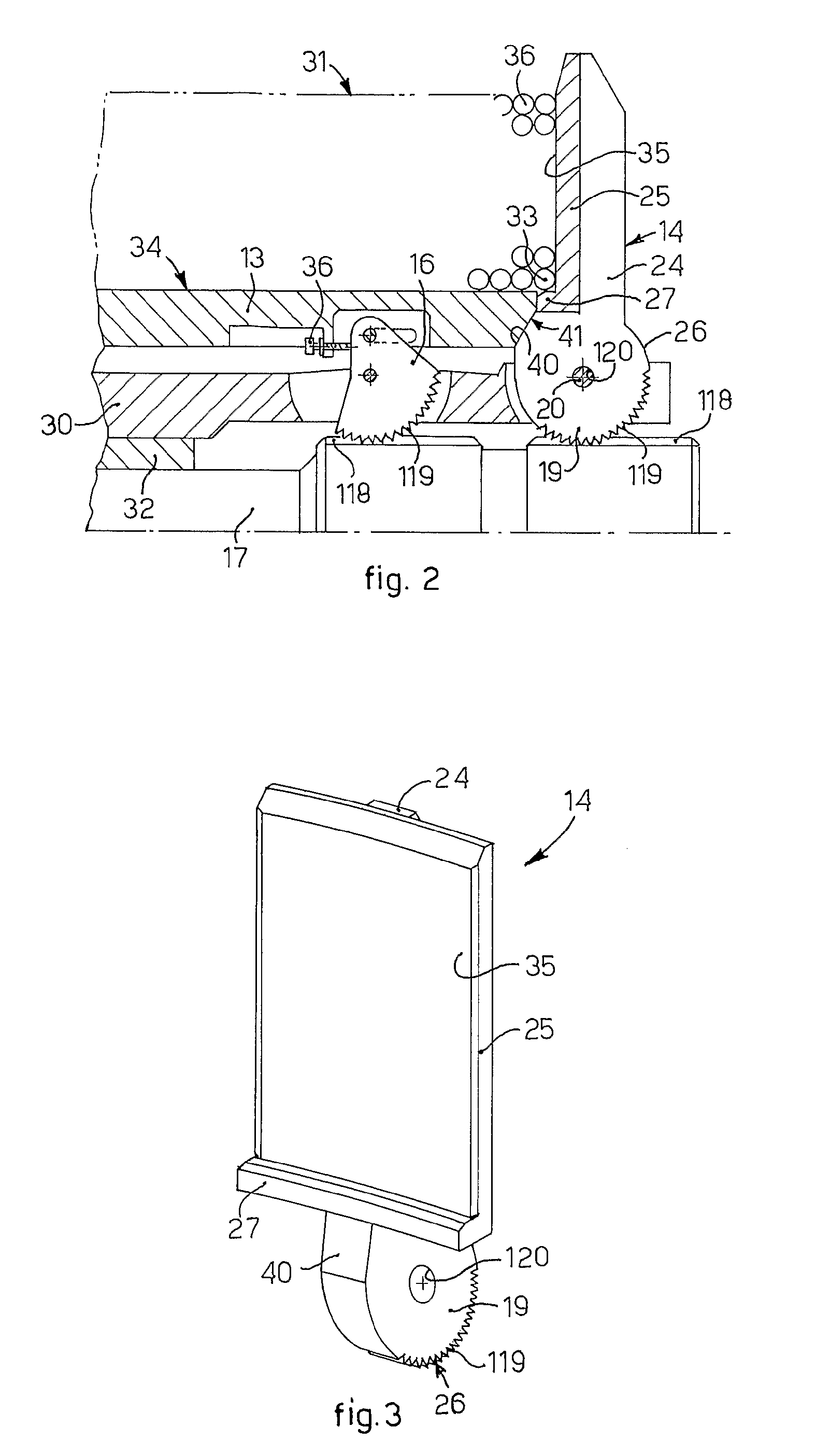
[0032]With reference to FIG. 1, a coiling device 10 according to the present invention is able to achieve a coil 31 of a long product 36, consisting for example of a metal wire with a circular transverse section.

[0033]The coiling device 10 comprises a mandrel 11 mounted rotatable and cantilevered, on a fixed cylindrical shaft 32, arranged coaxial with a longitudinal axis X. The rotation of the mandrel 11 with respect to the fixed shaft 32 is achieved in any known manner, for example by means of a drive member not shown in the drawings. Suitable known guide, positioning and drive means, and all else necessary, not shown in the drawings, are arranged between the mandrel 11 and the relative drive member.

[0034]The mandrel 11 comprises a containing flange 12, arranged perpendicular, or very angled, with respect to the longitudinal axis X. The flange 12 comprises a wall 135 which defines a lateral flank of the coil 31 to be formed. The wall 135 can be fixed, or mobile in an axial directio...


PUM

PropertyMeasurementUnit
diametersaaaaaaaaaa
diametersaaaaaaaaaa
geometric shapeaaaaaaaaaa

Abstract

Coiling device (10) and relative coiling method for rolled or drawn long products, comprising a mandrel (11), arranged cantilevered and rotatable with respect to a central longitudinal axis (X), and on which the long products are wound in adjacent and superimposed spirals (33), in order to form a compact coil (31) having the geometric shape of a circular ring with lateral flanks substantially orthogonal, or very angled, with respect to the central longitudinal axis (X). The mandrel (11) comprises a flange (12) substantially orthogonal, or very angled, with respect to the central longitudinal axis (X) which defines a first lateral flank of the coil (31). The mandrel (11) also comprises first arm elements (13) which define the cylindrical surface of the core that forms the coil (31), and second arm elements (14), opposite the flange (12), which define a second flank of the coil. The first and the second arm elements (13,14) are mobile between a first coil-forming position and a second coil-removal position.

Description

FIELD OF THE INVENTION[0001]The present invention concerns a coiling device and the relative coiling method for long metal products, ferrous or not, as obtained from drawing or rolling operations, whether done hot or cold. To be more exact, the invention concerns the coiling of wire, bars, flat strips, rods (smooth or ribbed), or tubes, having a transverse section that is round, square, rectangular, hexagonal or otherwise, of various sizes.[0002]To be more exact, the invention concerns the device to guide and contain the coiled product, on the winding mandrel, in order to contain it laterally and to impose on the forming coil the desired external form. The winding mandrel may have a horizontal, vertical or inclined axis of rotation.[0003]The invention is applied to coiling machines with cantilevered axis.BACKGROUND OF THE INVENTION[0004]In the state of the art, the problems connected to coiling, on a continuously rotating mandrel, a long metal product, either rolled or drawn, travel...

Claims


Application Information

Patent Timeline
Patent Type & Authority Patents(United States)
IPC IPC(8): B21C47/00B21C47/30B65H54/58
CPCB65H54/58B21C47/30
Inventor BORDIGNON, GIUSEPPEPAIARO, IVANDE LUCA, ANDREAPAOLONE, ROLANDO
Owner DANIELI & C OFF MEC SPA
Why Eureka
Eureka Blog
Learn More