Multi-frequency antenna with dual loops

a multi-frequency antenna and loop technology, applied in the direction of antennas, differentially interacting antenna combinations, antenna details, etc., can solve the problems of inconvenient system installation, inability to meet the requirements of larger bandwidth gradually, and inconvenient system installation, etc., to achieve the effect of increasing the capacity of the antenna

Active Publication Date: 2008-09-16
ADVANCED CONNECTEK INC
View PDF11 Cites 46 Cited by
  • Summary
  • Abstract
  • Description
  • Claims
  • Application Information

AI Technical Summary

Benefits of technology

[0013]The present invention is directed to a multi-frequency antenna with dual loops, which increases the capacity of the antenna through the coupling effect in the loops, so that the multi-frequency antenna has the characteristics of miniaturization and broad band at high frequency, thus achieving the bandwidth of 1710-2170 MHz and meeting the requirements of the bandwidths used in the systems such as DCS, PCS, and UMTS.
[0014]The present invention is also directed to a multi-frequency antenna with dual loops, which increases the capacity of the antenna through the coupling effect in the loops, so that the multi-frequency antenna has the characteristics of miniaturization and broad band at low frequency, thus achieving the bandwidth of 824-960 MHz and meeting the requirements of the bandwidths used in the systems such as AMPS and GSM.
[0015]The present invention is still directed to a multi-frequency antenna with dual loops, which employs a T-shaped radiator having a first arm and a second arm of unequal lengths and two grounded L-shaped radiators to form two different loops, thereby achieving the effects of adjusting frequency and matching impedance by adding coupling capacitance in the loops.
[0017]According to the present invention, the T-shaped radiator, the first and the second grounded L-shaped radiators are employed to form two independent loops, which allow the antenna to operate in various frequency bands. Therefore, not only the bandwidth is broadened, but also a significant frequency downconversion is achieved. Meanwhile, the multi-frequency function can be achieved by using the structure of a T-shaped radiator and two L-shaped radiator only, thus greatly reducing the difficulty and cost of fabricating the product.

Problems solved by technology

However, this also brings troubles and inconvenience to system suppliers and consumers due to different systems, such as GSM900, DCS1800, and PCS1900, adopting different frequencies.
Thus, the conventional planar inverted-F antenna (PIFA) cannot meet the requirements of larger bandwidth gradually.
Therefore, the structure is not suitable for a compact device with a limited space for accommodating the antenna.

Method used


Image

  • Multi-frequency antenna with dual loops
  • Multi-frequency antenna with dual loops
  • Multi-frequency antenna with dual loops

Examples


first embodiment

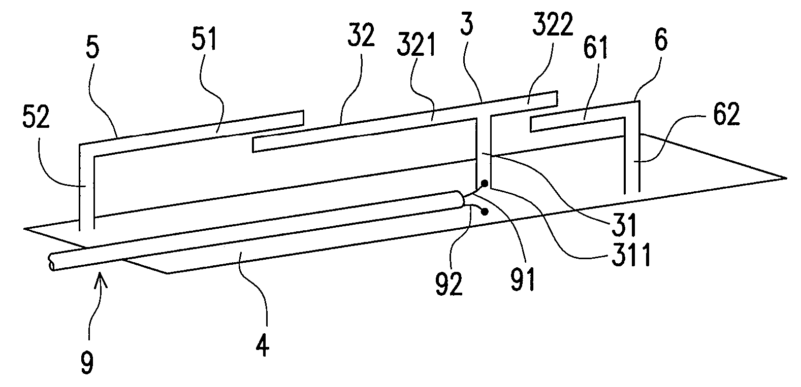
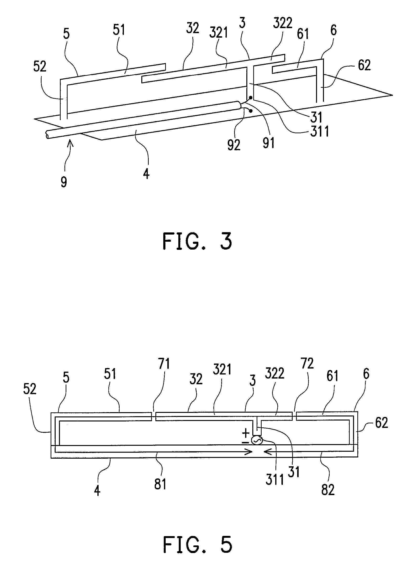
[0031]Referring to FIG. 3, the multi-frequency antenna in the present invention includes a T-shaped radiator 3, a first L-shaped radiator 5 and a second L-shaped radiator 6, a ground plane 4, and a feeder cable 9. In this embodiment, a first arm 321 and a second arm 322 of the T-shaped radiator 3 are suspended above the ground plane 4, but the bottom 311 of a first portion 31 of the T-shaped radiator 3 is connected with a positive signal wire 91 of the feeder cable 9 for transmitting an electrical signal to the T-shaped radiator 3, and the negative signal wire 92 of the feeder cable 9 is electrically connected with the ground plane 4.

[0032]The two L-shaped radiators includes a first L-shaped radiator 5 and a second L-shaped radiator 6 opposite to the first L-shaped radiator 5. The longer portion 51 of the first L-shaped radiator 5 and the longer portion 61 of the second L-shaped radiator 6 point to each other and are spaced away from and parallel to the second portion 32 of the T-sh...

second embodiment

[0038]Referring to FIG. 6, the multi-frequency antenna of the present invention includes a T-shaped radiator 3, a first L-shaped radiator 5 and a second L-shaped radiator 6, a ground plane 4, and a feeder cable 9. The T-shaped radiator 3, the first L-shaped radiator 5, and the second L-shaped radiator 6 are elongated metal element. In this embodiment, a first arm 321 and a second arm 322 of the T-shaped radiator 3 are suspended above the ground plane 4, but the bottom 311 of the first portion 31 of the T-shaped radiator 3 is connected with the positive signal wire 91 of the feeder cable 9 for transmitting an electrical signal to the T-shaped radiator 3, and the negative signal wire 92 of the feeder cable 9 is electrically connected with the ground plane 4.

[0039]The two L-shaped radiators include a first L-shaped radiator 5 and a second L-shaped radiator 6 opposite to the first L-shaped radiator 5. The longer portion 51 of the first L-shaped radiator 5 and the longer portion 61 of th...

third embodiment

[0040]Referring to FIG. 7, the multi-frequency antenna in the present invention includes a T-shaped radiator 3, a first L-shaped radiator 5 and a second L-shaped radiator 6, a ground plane 4, and a feeder cable 9. The T-shaped radiator 3, the first L-shaped radiator 5, the second L-shaped radiator 6, and the ground plane 4 are all obtained by punching metal sheets. In this embodiment, a first arm 321 and a second arm 322 of the T-shaped radiator 3 are suspended above the ground plane 4, but the bottom 311 of the first portion 31 of the T-shaped radiator 3 is connected with the positive signal wire 91 of the feeder cable 9 for transmitting an electrical signal to the T-shaped radiator 3, and the negative signal wire 92 of the feeder cable 9 is electrically connected with the ground plane 4.

[0041]The two L-shaped radiators include a first L-shaped radiator 5 and a second L-shaped radiator 6 opposite to the first L-shaped radiator 5. The longer portion 51 of the first L-shaped radiator...


PUM


Abstract

A multi-frequency antenna with dual loops is provided. The antenna includes a T-shaped radiator having a first arm and a second arm of unequal lengths as a main body, and two grounded L-shaped radiators, so as to form dual loops. Thus, the antenna can operate in a high-frequency operation mode and a low-frequency operation mode. With the dual loops, the antenna obtains enough bandwidths at high frequency, and also meets the requirements of low frequency. More specific, the antenna meets the requirements of high-frequency systems, such as DCS / PCS / UMTS and those of low-frequency systems, such as AMPS / GSM.

Description

CROSS-REFERENCE TO RELATED APPLICATION[0001]This application claims the priority benefit of Taiwan application serial no. 95120597, filed Jun. 9, 2006. All disclosure of the Taiwan application is incorporated herein by reference.BACKGROUND OF THE INVENTION[0002]1. Field of the Invention[0003]The present invention relates to a multi-frequency antenna with dual loops. More particularly, the present invention relates to a multi-frequency antenna which can operate in two different frequency bands with the dual loops thereof.[0004]2. Description of Related Art[0005]The personal mobile communications technology has already proven its huge potential and business opportunity in the wireless communications industry. In the course of advancement, various systems adopting different technologies and frequency bands have been developed and used in different areas and markets. However, this also brings troubles and inconvenience to system suppliers and consumers due to different systems, such as ...

Claims


Application Information

Patent Timeline
Patent Type & Authority Patents(United States)
IPC IPC(8): H01Q1/24H01Q5/15
CPCH01Q1/38H01Q5/371H01Q21/29H01Q7/00
Inventor CHUNG, MING-HSUNCHIU, TSUNG-WENHSIAO, FU-RENLIN, YU-CHINGLAN, CHUN-CHING
Owner ADVANCED CONNECTEK INC
Why Eureka
Try Eureka