
Keyboard apparatus

a keyboard and keyboard technology, applied in the field of keyboard apparatus, can solve the problems of increasing the number of components, and requiring many man-hours, and achieve the effect of reducing the depth of the keyboard apparatus and simple operation

Active Publication Date: 2008-09-23
YAMAHA CORP
View PDF17 Cites 9 Cited by
  • Summary
  • Abstract
  • Description
  • Claims
  • Application Information

AI Technical Summary

Benefits of technology

The present invention provides a keyboard apparatus that can be easily mounted onto a key frame with a simple operation. The keyboard apparatus includes a key unit with a plurality of key main bodies that are pivotally supported by a common base end via thin plate-like hinges. The common base end is fixedly supported by the key frame using elastic deformation of the hinges and the base end support. The key unit can be stacked and mounted onto the key frame, and the position of the key unit can be restricted using position restriction means. The keyboard apparatus is stable and secure, and its depth size can be reduced.

Problems solved by technology

As a consequence, the keyboard apparatus is large in depth size.
This poses a problem that many man-hours are required in mounting the key unit to the key frame and the number of component parts increases.
Nevertheless, the keyboard apparatus disclosed in Japanese Laid-open Publication No. 2001-215968 is constructed to threadedly engage screws from the rear side of the keyboard apparatus, which requires an additional step of such as inverting the keyboard apparatus front to back, posing a problem of poor workability.

Method used


Image

  • Keyboard apparatus
  • Keyboard apparatus
  • Keyboard apparatus

Examples


first embodiment

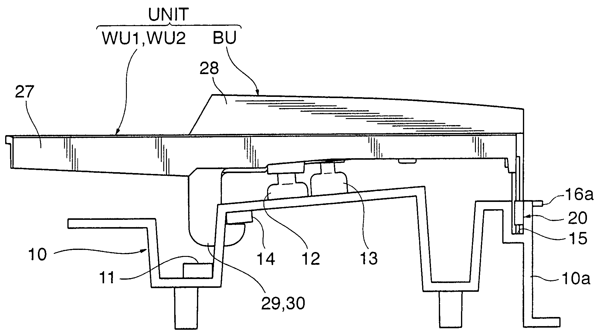
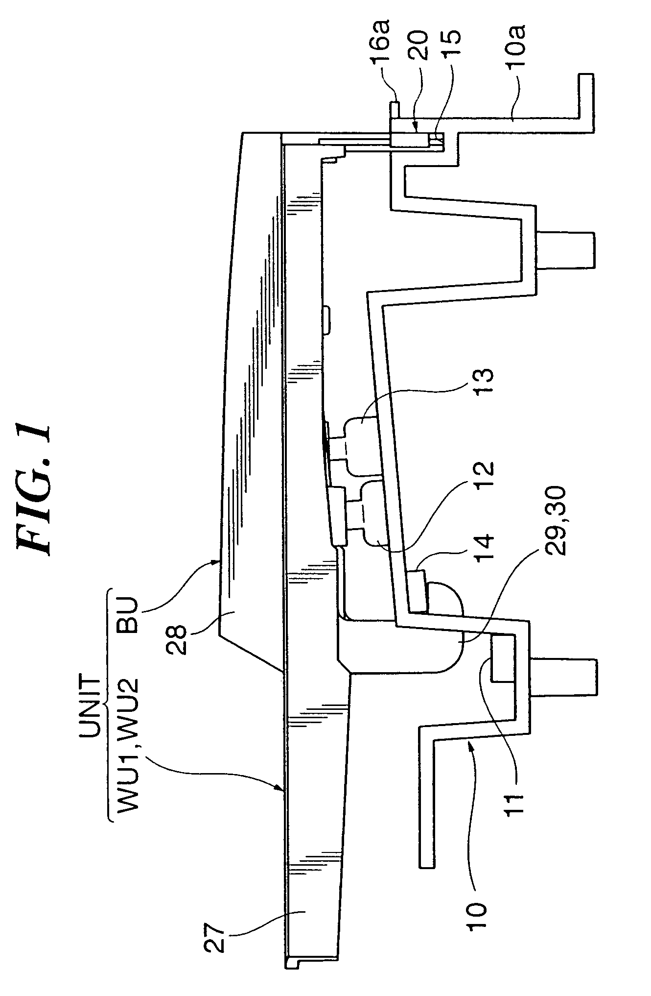
[0035]FIG. 1 is a right side view showing an essential part of a keyboard apparatus according to a first embodiment of the present invention. This keyboard apparatus is constructed as an electronic musical keyboard instrument, and includes a key frame 10 to which a key unit UNT is mounted. In the following, a side of the keyboard apparatus toward a player (the left side in FIG. 1) will be referred as the front side, and the left-to-right direction will be determined in reference to the player.

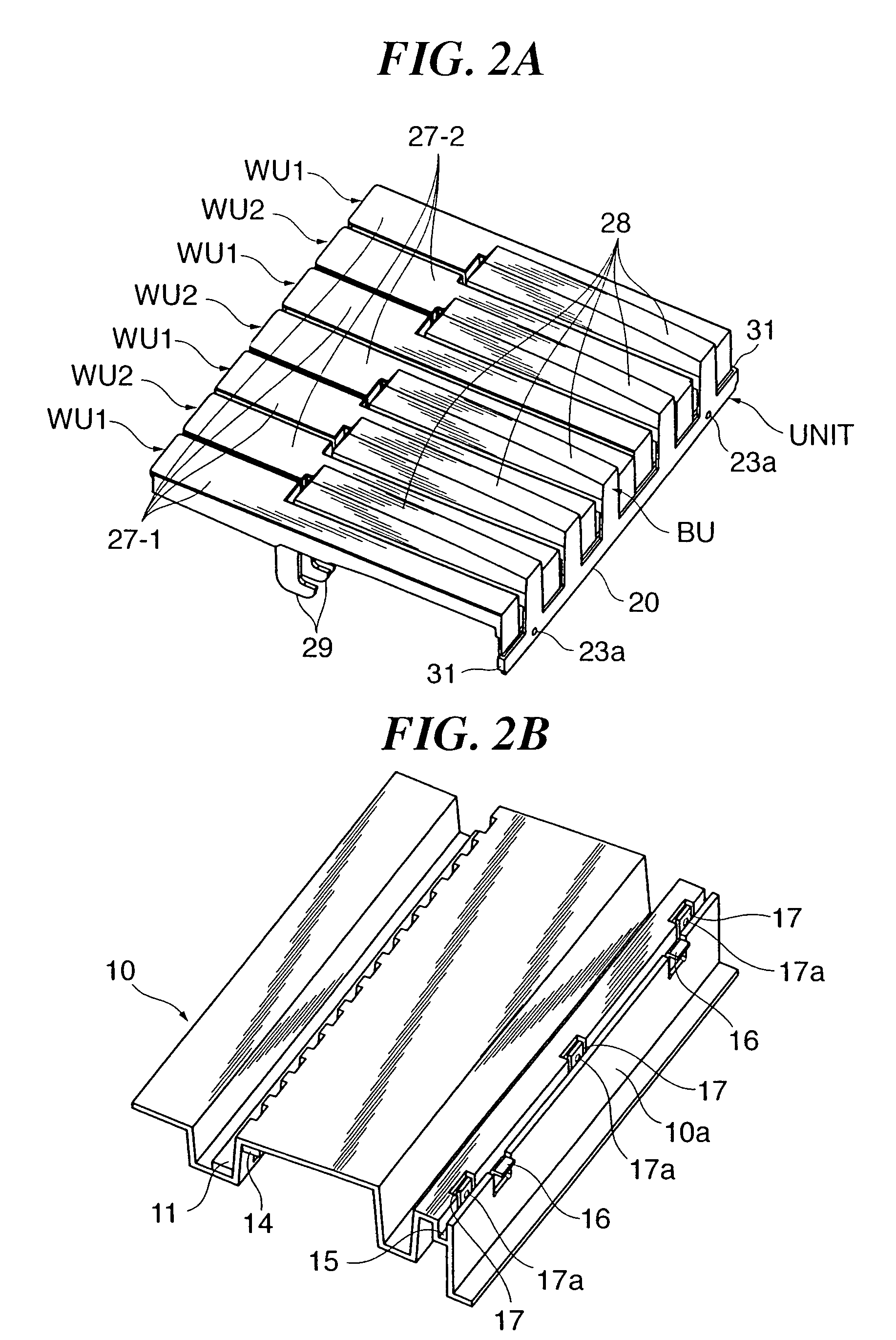
[0036]FIG. 2A is a perspective view of the key unit UNT, and FIG. 2B is a perspective view of the key frame 10. As shown in FIG. 2A, the key unit UNT is constructed to cover one octave, for instance, and includes first and second white key units WU1, WU2 each having a plurality of white key main bodies 27 and a black key unit BU having a plurality of black key main bodies 28, these three units being assembled in a stacked relation. The key frame 10 is made of resin or metal, is constructed into...

second embodiment

[0068]FIG. 7 is a perspective view showing a one-octave part of a keyboard apparatus according to a second embodiment of the present invention. The keyboard apparatus of this embodiment is comprised of a key frame 110 corresponding to the above described key frame 10 to which is mounted a key unit UNT2 corresponding to the key unit UNT. The key unit UNT2 is formed by first and second white key units WU11, WU12 and a black key unit BU 10, which are assembled in a stacked relation.

[0069]FIG. 8 is a perspective view of the white key unit WU11. FIG. 9A is a side view showing rear halves of the white key units WU11, WU12, the black key unit BU10, and the key unit UNT2. FIG. 9B is a right side view showing a rear end of the keyboard apparatus. FIG. 10 is a plan view separately showing the key frame 110 and the key unit UNT 2 in a state before they are assembled together. In FIG. 10, the rear ends of the key units WU11, WU12, BU10 are shown in this order from the left side of FIG. 10, and ...

third embodiment

[0081]In the above described first and second embodiments, protrusions and fitting holes are provided between adjacent ones of the common-to-white-keys base end, the common-to-black-keys base end, and the key frame. However, one protrusion may be fitted to two or more fitting holes.

[0082]FIG. 11A is a right side view showing a rear end of a keyboard apparatus according to a third embodiment. The keyboard apparatus of this embodiment includes a key frame 210 corresponding to the key frame 10, to which a key unit UNT3 corresponding to the key unit UNT is mounted. FIG. 11B is a view schematically showing an arrangement in which a common-to-all-keys base end 220 is assembled to the key frame 210.

[0083]As shown in FIGS. 11A and 11B, in the key unit UNT3, first and second common-to-white-keys base end 221, 222, and a common-to-black-keys base end 223 corresponding the above described first and second common-to-white-keys base end 21, 22 and the common-to-black-keys base end 23 are stacked...


PUM


Abstract

A keyboard apparatus constructed to be capable of reducing the depth size thereof and permitting a key unit to be mounted to a key frame with a simple operation. Hinges are extended downward from rear ends of black key main bodies of a black key unit in the vertical direction, and are connected at their lower ends to a common-to-black-keys base end. The black key main bodies are pivotable via the hinges relative to the common-to-black-keys base end in the key depression / release direction. Similarly, white key main bodies of first and second white key units are pivotable via hinges relative to a common base end in the vertical direction. The key frame is formed at its rear portion with a recessed groove over the entire width of all keys and formed with elastic members extending in the front-to-rear direction on the front and rear sides of the recessed groove. Using elastic deformations of the elastic members, a common-to-all-keys base end of the key unit is fitted and fixed to the recessed groove.

Description

BACKGROUND OF THE INVENTION[0001]1. Field of the Invention[0002]The present invention relates to a keyboard apparatus having a key frame to which is mounted a key unit that includes a plurality of key main bodies supported via hinges for pivotal motion by a common base end.[0003]2. Description of the Related Art[0004]Conventionally, there has been known a keyboard apparatus in which a key frame is mounted with a key unit having a plurality of key main bodies supported for pivotal motion by a common base end via thin plate-like hinges. For example, Japanese Patent No. 2628656 discloses a key unit comprised of two white key units and one black key unit, which are disposed in a stacked relation. The white and black key units each have hinges horizontally extended rearward substantially parallel to key depression surfaces of the keys, and therefore, these key units are long in size in a longitudinal direction of keys. As a consequence, the keyboard apparatus is large in depth size.[0005...

Claims


Application Information

Patent Timeline
Patent Type & Authority Patents(United States)
IPC IPC(8): H01H13/70
CPCG10H1/344G10H2220/275
Inventor WATANABE, KEISUKE
Owner YAMAHA CORP
Learn More