V-type engine air intake device

a technology of air intake device and internal combustion engine, which is applied in the direction of machines/engines, combustion-air/fuel-air treatment, and feed systems, etc., can solve the problems of interfering with each other in communication passages of the intake air supplied from the throttle body through the left and right air induction arrangement, and achieve the effect of increasing the intake resistance and preventing the increase of engine outpu

Active Publication Date: 2008-09-30
NISSAN MOTOR CO LTD
View PDF2 Cites 0 Cited by
  • Summary
  • Abstract
  • Description
  • Claims
  • Application Information

AI Technical Summary

Benefits of technology

[0007]In the intake manifold (intake device) disclosed in the above mentioned publication, communication passages extending from the left and right are arranged facing opposite each other with a resonance switching valve in-between. When the resonance switching valve is opened during low engine speeds, the intake air supplied from the throttle bodies through the left and right air induction arrangements collide (interfere) with each other in the communication passages. As a result, the intake resistance increases, and the engine output is prevented from increasing.
[0008]The object of the present invention is to reduce the resistance to the flow of intake air from the throttle bodies to the intake ports in an intake device of a V-type internal combustion engine. This resistance to the flow of intake air from the throttle bodies to the intake ports will hereinafter be referred to as “intake resistance”.

Problems solved by technology

When the resonance switching valve is opened during low engine speeds, the intake air supplied from the throttle bodies through the left and right air induction arrangements collide (interfere) with each other in the communication passages.

Method used


Image

  • V-type engine air intake device
  • V-type engine air intake device
  • V-type engine air intake device

Examples


Embodiment Construction

[0023]Selected embodiments of the present invention will now be explained with reference to the drawings. It will be apparent to those skilled in the art from this disclosure that the following descriptions of the embodiments of the present invention are provided for illustration only and not for the purpose of limiting the invention as defined by the appended claims and their equivalents.

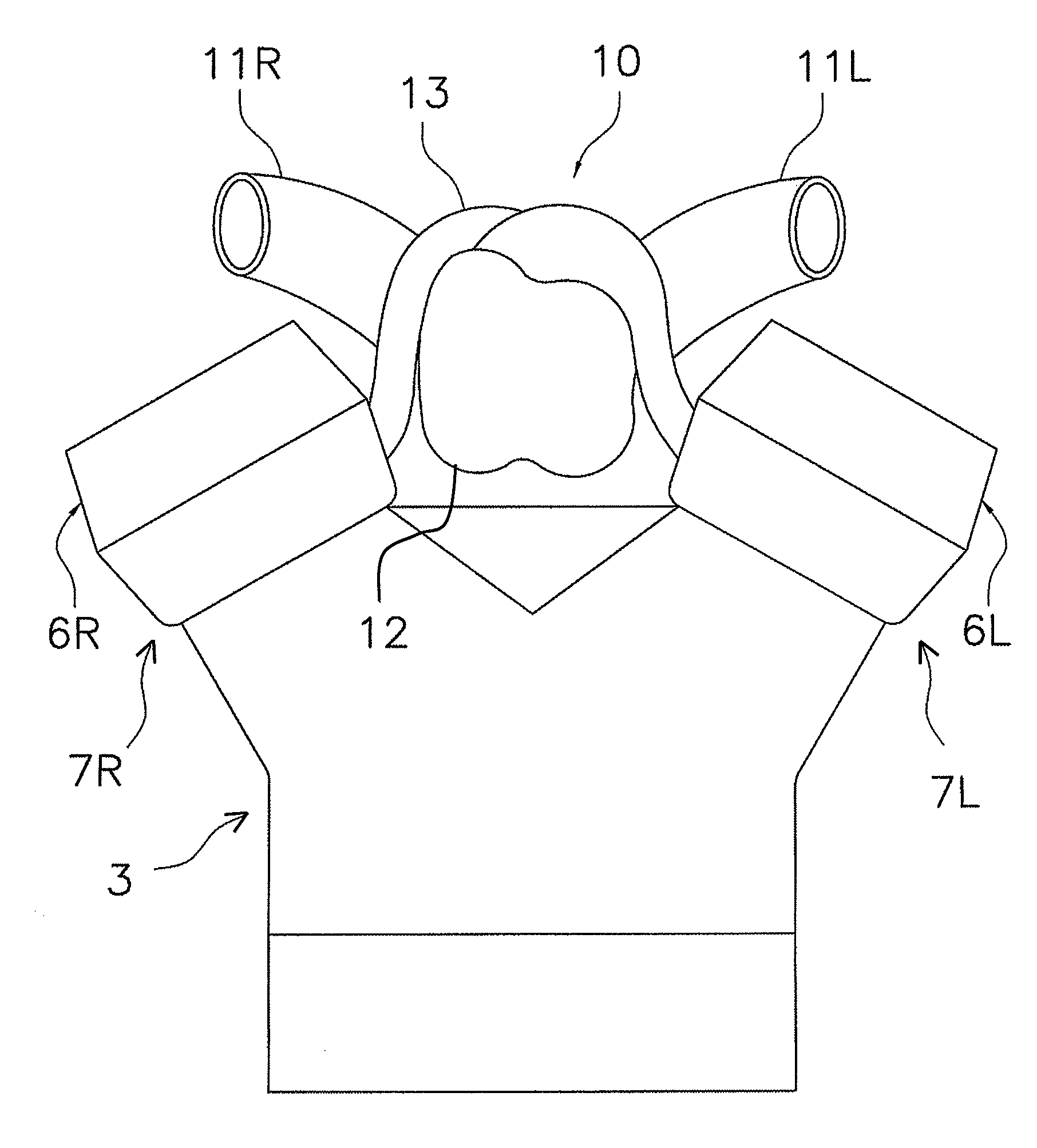
[0024]Referring initially to FIG. 1, a simplified front elevational view of a V-type internal combustion engine is illustrated that has a cylinder block 3 with an intake device 10 in accordance with an embodiment of the present invention. In the illustrated embodiments, the V-type internal combustion engine can be a gasoline engine or a diesel engine. Additionally, in the illustrated embodiments, it is assumed that the movement direction of the vehicle is the forward (forward) direction and such other direction terms as left, right, forward, rearward, lateral, and longitudinal are defined based on ...


PUM


Abstract

A V-type engine air intake device is provided for a V-type internal combustion engine. The V-type engine air intake device has a volume chamber, a first intake pipe, a second intake pipe and a plurality of curved branch pipes. The first intake pipe has a first outlet end connected to a first intake opening of the volume chamber. The second intake pipe has a second outlet end connected to a second intake opening of the volume chamber. The first and second outlet ends are arranged with first and second center outlet axes where that the first and second intake pipes connect to the volume chamber. The second center outlet axis is non-coincident with the first center outlet axis. The branch pipes each has an inlet end that opens inside the volume chamber in a substantially vertical downward direction.

Description

CROSS-REFERENCE TO RELATED APPLICATIONS[0001]This application claims priority to Japanese Patent Application No. 2006-144298, filed on May 24, 2006. The entire disclosure of Japanese Patent Application No. 2006-144298 is hereby incorporated herein by reference.BACKGROUND OF THE INVENTION[0002]1. Field of the Invention[0003]The present invention relates to an intake device for an internal combustion engine. More particularly, the present invention relates to an intake device for a V-type internal combustion engine equipped with two intake devices for a plurality of cylinder banks.[0004]2. Background Information[0005]One typical type of intake device for a V-type internal combustion engine has two air induction passage arrangements, i.e., a left air induction arrangement and a right air induction arrangement, serving to deliver intake air from a pair of left and right throttle bodies (e.g., Japanese Laid-Open Patent Publication No. 2000-54845).[0006]In view of the above, it will be ap...

Claims


Application Information

Patent Timeline
Patent Type & Authority Patents(United States)
IPC IPC(8): F02M35/00
CPCF02M35/10032F02M35/116F02M35/10039
Inventor SASAKI, JUNYA
Owner NISSAN MOTOR CO LTD
Why Eureka
Try Eureka