Air tightness detector for hydraulic shock absorber

A technology of hydraulic shock absorbers and detectors, which is used in fluid tightness testing, fluid tightness measurement using liquid/vacuum degree, and testing of machine/structural components, etc. It can solve complicated steps, danger, brake failure, etc. problems, to achieve the effect of improving the absorption speed and facilitating the measurement and statistics

Pending Publication Date: 2022-03-01
彭扬
View PDF8 Cites 0 Cited by
  • Summary
  • Abstract
  • Description
  • Claims
  • Application Information

AI Technical Summary

Problems solved by technology

[0002] Motorcycle front shock absorbers are used all the year round. Due to broken oil seals or excessive pipe diameter gaps, oil leakage will occur. If the amount of oil leakage is too large, if it is not discovered in time, the oil will drip onto the brake disc, which will easily lead to brake failure. It is very dangerous. Therefore, it is necessary to regularly test the shock absorber to eliminate hidden dangers in time. The existing shock absorber sealing test usually requires dismantling the shock absorber module, and the steps are cumbersome. The main problem to be solved by the present invention is how to quickly and efficiently Check the airtightness of the shock absorber

Method used


Image

  • Air tightness detector for hydraulic shock absorber
  • Air tightness detector for hydraulic shock absorber
  • Air tightness detector for hydraulic shock absorber

Examples


Embodiment Construction

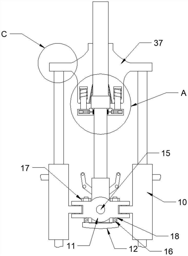
[0023] Combine below Figure 1-5 The present invention is described in detail, wherein, for the convenience of description, the orientations mentioned below are defined as follows: figure 1 The up, down, left, right, front and back directions of the projection relationship itself are the same.

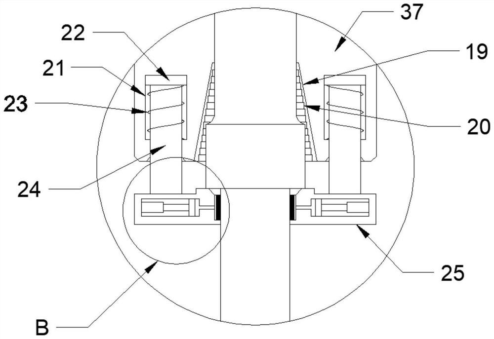
[0024] A hydraulic shock absorber air tightness detector described in conjunction with accompanying drawings 1-5 includes a lower locking body 11, a supporting plate 12 is provided for sliding down of the lower locking body 11, and a The shaft 15 is fixed, and the left and right sides of the lower locking body 11 are rotated with a hydraulic rod 10, and the shaft on the upper side of the hydraulic rod 10 is provided with an upper locking body 37, and a tapered groove 19 is arranged in the middle of the upper locking body 37, The inner wall of the tapered groove 19 is provided with a locking groove 20, the lower side of the upper locking body 37 slides and is provided with an adjusting...


PUM


Abstract

The invention relates to the technical field of hydraulic shock absorption detection, and discloses a hydraulic shock absorber air tightness detector which comprises a lower locking body, a supporting plate is arranged below the lower locking body in a sliding mode, a fixing shaft is arranged in the middle of the lower locking body, hydraulic rods are rotationally arranged on the left side and the right side of the lower locking body, and an upper locking body is arranged on a shaft on the upper sides of the hydraulic rods. A conical groove is formed in the middle of the upper locking body, a clamping groove is formed in the inner wall of the conical groove, a hose base, a detection body, a thin hose, a detection cavity, a driven plate and the like are arranged, the thin hose is tightly attached to the position close to an oil seal of the shock absorber, the shock absorber is repeatedly compressed, and the severe working condition of the shock absorber is simulated; the thin hose is sealed by the oil, so that the air inlet resistance of the air inlet is increased, and the driving rod moves to drive the driven plate to move.

Description

technical field [0001] The invention relates to the technical field of hydraulic shock absorber detection, in particular to a hydraulic shock absorber air tightness detector. Background technique [0002] Motorcycle front shock absorbers are used all the year round. Due to broken oil seals or excessive pipe diameter gaps, oil leakage will occur. If the amount of oil leakage is too large, if it is not discovered in time, the oil will drip onto the brake disc, which will easily lead to brake failure. It is very dangerous. Therefore, it is necessary to regularly test the shock absorber to eliminate hidden dangers in time. The existing shock absorber sealing test usually requires dismantling the shock absorber module, and the steps are cumbersome. The main problem to be solved by the present invention is how to quickly and efficiently Check the airtightness of the shock absorber. Contents of the invention [0003] The object of the present invention is to provide a hydraulic ...

Claims


Application Information

Patent Timeline
Patent Type & Authority Applications(China)
IPC IPC(8): G01M3/32
CPCG01M3/3218
Inventor 彭扬
Owner 彭扬
Why Eureka
Try Eureka