hc adsorption device

An adsorption device and power device technology, applied in the direction of charging system, fuel air filter, combustion air/combustion-air treatment, etc., can solve the problem of increasing intake resistance, increasing intake system intake resistance, adsorption Low efficiency and other problems to achieve the effect of avoiding air intake resistance, ensuring the use effect, and good use effect

Active Publication Date: 2019-12-17
GREAT WALL MOTOR CO LTD
View PDF4 Cites 0 Cited by
  • Summary
  • Abstract
  • Description
  • Claims
  • Application Information

AI Technical Summary

Problems solved by technology

Although the above-mentioned adsorption structures can achieve the purpose of reducing the discharge of hydrocarbons, the filter element structure will increase the intake resistance of the intake system during use, and the insertion pipe type also has the problem of increasing the intake resistance, while the inner wall structure Then there is the disadvantage of low adsorption efficiency

Method used


Image

  • hc adsorption device
  • hc adsorption device
  • hc adsorption device

Examples


Embodiment 1

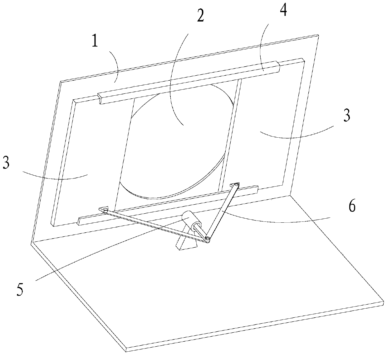
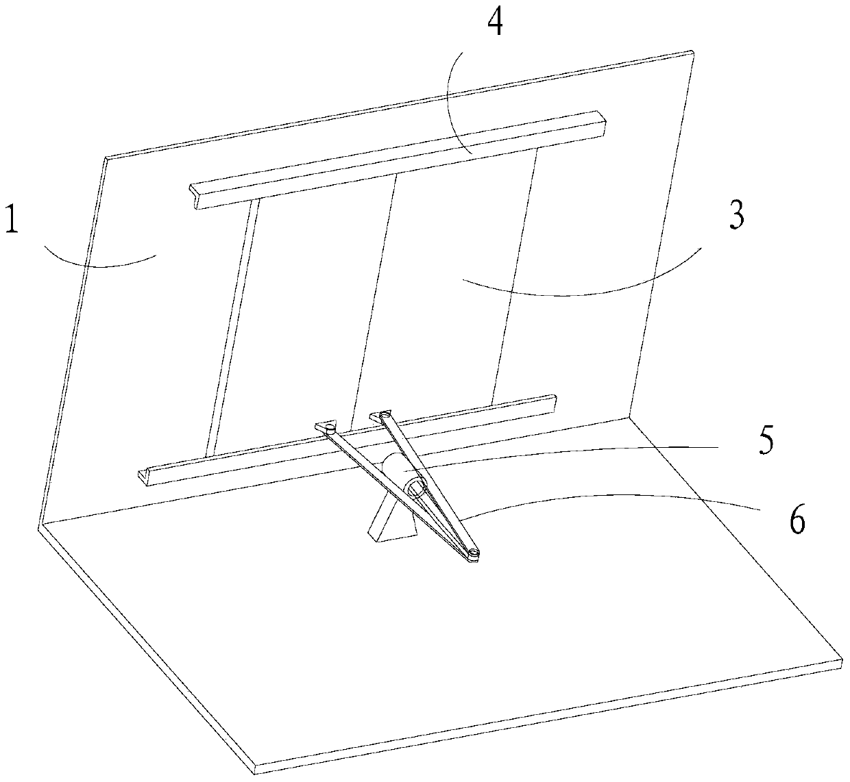
[0029] The invention relates to an HC adsorption device, which is cooperatingly arranged on the air intake pipe of the vehicle air intake system, and includes a blocking part cooperating with the air intake pipe, and is fixedly arranged relative to the vehicle and forms a drive with the blocking part. Connected drive mechanism. The blocking portion has a blocking surface not smaller than the cross-sectional area of ​​the intake pipe, and when the engine is working, the blocking portion can fully open the intake pipe due to the drive of the driving mechanism, so that the intake pipe is free from intake air. The open state that blocks entry. When the engine stops working, the blocking part can block the intake pipe through the blocking surface due to the drive of the drive mechanism, so that the intake pipe is in a closed state.

[0030] The HC adsorption device can fully open the air intake pipe when the engine is working through the setting of the blocking part and the drivin...

Embodiment 2

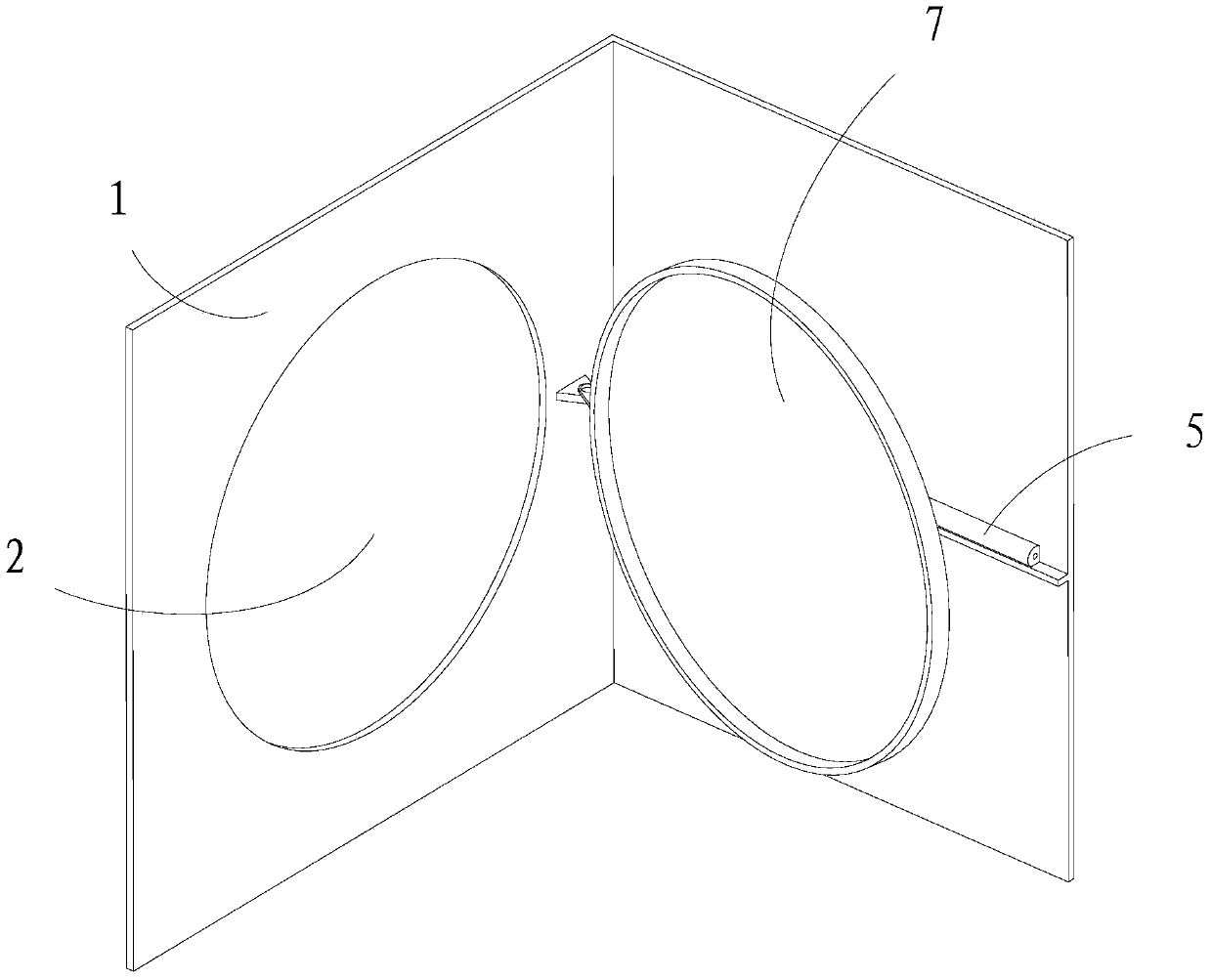
[0038] This embodiment relates to an HC adsorption device, which has roughly the same structure as the HC adsorption device in Embodiment 1, except that image 3 and Figure 4 As shown in , the blocking part in this embodiment is an overturned sealing unit 7 pivotally connected to the intake pipe 1 , and the overturned sealing unit 7 is formed with a blocking surface unit for sealing the intake section 2 . The drive mechanism of this embodiment still includes the electromagnetic valve 5 arranged on the vehicle, and the connecting rod 6 hinged between the electromagnetic valve 5 and the overturning blocking unit 7, which can drive the overturning blocking unit 7 under the action of the electromagnetic valve 5 Turn over relative to the intake pipe 1 to block the intake section 2 or open the intake section 2.

[0039] In this embodiment, besides the electromagnetic valve 5 , other power devices such as cylinders or linear motors can of course also be used, and the plugging surfa...


PUM


Abstract

The invention provides an HC adsorption device which is arranged on an air inlet pipeline of a vehicle air intake system in a matched mode. The HC adsorption device comprises a blocking part matched with the air inlet pipeline and a driving mechanism, and the driving mechanism is fixedly arranged relative to a vehicle and is in driving connection with the blocking part. The blocking part is provided with a blocking surface with the area not less than the cross sectional area of the air inlet pipeline. When the engine operates, the blocking part is driven by the driving mechanism to completely open the air inlet pipeline so as to enable air flow to go into an opening state without blockage. When the engine stops operating, the blocking part is driven by the driving mechanism to enable the air inlet pipeline to be blocked through the blocking surface in a closed state. The HC adsorption device cannot affect air intake of the air intake system, can prevent hydrocarbon from being evaporated outwards when the engine stops, can avoid the defects of increased air intake resistance, poor control effect and the like existing in an existing adsorption structure and accordingly has a good using effect.

Description

technical field [0001] The invention relates to the technical field of automotive air intake system components, in particular to an HC adsorption device. Background technique [0002] With the increasing requirements of vehicle emission regulations, controlling the amount of hydrocarbons (HC) evaporated from the intake system when the vehicle is stopped has become an important research topic for various vehicle manufacturers. At present, the control of the evaporation of hydrocarbons in the intake system is mainly realized by means of adsorption, and the arrangement of the adsorption structure in the intake system mainly includes three types: filter element type, pipe insertion type and inner wall type. Although the above-mentioned adsorption structures can achieve the purpose of reducing the discharge of hydrocarbons, the filter element structure will increase the intake resistance of the intake system during use, and the insertion pipe type also has the problem of increasi...

Claims


Application Information

Patent Timeline
Patent Type & Authority Patents(China)
IPC IPC(8): F02M35/02
CPCF02M35/0218
Inventor 韩洪豹刘志强李宇管振海任正芳牛荣平李峰张玉成翁耳楠
Owner GREAT WALL MOTOR CO LTD
Why Eureka
Try Eureka