Air-blowing type micro gas turbine and starting method thereof
A micro gas turbine and air-blown technology, which is applied in the direction of gas turbine devices, combustion air/combustion-air treatment, machines/engines, etc., can solve the problems of high processing difficulty, reduced service life, high quality, etc., and achieve easy coaxiality Guaranteed, low processing difficulty, large air flow effect
- Summary
- Abstract
- Description
- Claims
- Application Information
AI Technical Summary
Problems solved by technology
Method used
Image
Examples
Embodiment 1
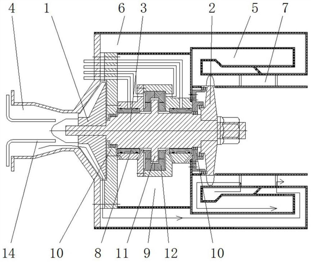
[0031] like figure 1 As shown, an air-blown micro gas turbine includes a compressor 1, a turbine 2, a rotating shaft 3, an intake passage 4, and a combustion chamber 5; the compressor 1 and the turbine 2 are respectively sleeved on the front end and the end of the rotating shaft 3 The front end of the compressor 1 is surrounded by a shell that surrounds the air intake passage 4, the outlet of the compressor 1 is connected to the combustion chamber 5 through the outlet passage 6, and the rim of the turbine 2 is arranged in the exhaust passage 7 of the combustion chamber 5, and the combustion chamber 5. The high-temperature and high-pressure gas ejected from the exhaust passage 7 is sprayed on the end face of the turbine 2 to drive the turbine 2 to rotate and do work; the rotating shaft 3 is supported in the stator by the radial bearing 8; each bearing is arranged on the rotating shaft between the compressor 1 and the turbine 2 On the shaft section, a bearing chamber 9 is formed...
Embodiment 2
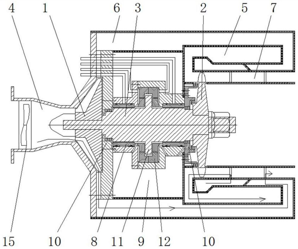
[0042] like figure 2 As shown, an air-blown micro gas turbine includes a compressor 1, a turbine 2, a rotating shaft 3, an intake passage 4, and a combustion chamber 5; the compressor 1 and the turbine 2 are respectively sleeved on the front end and the end of the rotating shaft 3 The front end of the compressor 1 is surrounded by a shell that surrounds the air intake passage 4, the outlet of the compressor 1 is connected to the combustion chamber 5 through the outlet passage 6, and the rim of the turbine 2 is arranged in the exhaust passage 7 of the combustion chamber 5, and the combustion chamber 5. The high-temperature and high-pressure gas ejected from the exhaust passage 7 is sprayed on the end face of the turbine 2 to drive the turbine 2 to rotate and do work; the rotating shaft 3 is supported in the stator by the radial bearing 8; each bearing is arranged on the rotating shaft between the compressor 1 and the turbine 2 On the shaft section, a bearing chamber 9 is forme...
Embodiment 3
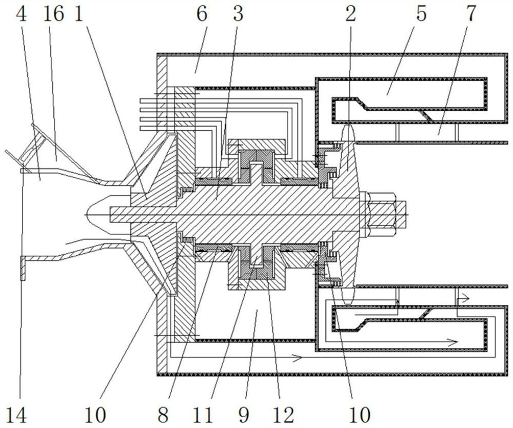
[0053] like image 3 As shown, an air-blown micro gas turbine includes a compressor 1, a turbine 2, a rotating shaft 3, an intake passage 4, and a combustion chamber 5; the compressor 1 and the turbine 2 are respectively sleeved on the front end and the end of the rotating shaft 3 The front end of the compressor 1 is surrounded by a shell that surrounds the air intake passage 4, the outlet of the compressor 1 is connected to the combustion chamber 5 through the outlet passage 6, and the rim of the turbine 2 is arranged in the exhaust passage 7 of the combustion chamber 5, and the combustion chamber 5. The high-temperature and high-pressure gas ejected from the exhaust passage 7 is sprayed on the end face of the turbine 2 to drive the turbine 2 to rotate and do work; the rotating shaft 3 is supported in the stator by the radial bearing 8; each bearing is arranged on the rotating shaft between the compressor 1 and the turbine 2 On the shaft section, a bearing chamber 9 is formed...
PUM
 Abstract
Description
Claims
Application Information
 - R&D
- Intellectual Property
- Life Sciences
- Materials
- Tech Scout
- Unparalleled Data Quality
- Higher Quality Content
- 60% Fewer Hallucinations
Browse by: Latest US Patents, China's latest patents, Technical Efficacy Thesaurus, Application Domain, Technology Topic, Popular Technical Reports.
© 2025 PatSnap. All rights reserved.Legal|Privacy policy|Modern Slavery Act Transparency Statement|Sitemap|About US| Contact US: help@patsnap.com


