Heat sink fastener

a technology of heat sink and fastener, which is applied in the direction of cooling/ventilation/heating modification, semiconductor/solid-state device details, semiconductor devices, etc., can solve the problems of increasing the complexity and cost of the structure of the fastener, prone to wedge the edge of the cam in the slot, and reducing the service life of the fastener. , to achieve the effect of relieving the force and relaxing the tension

Inactive Publication Date: 2008-09-30
HON HAI PRECISION IND CO LTD +1
View PDF7 Cites 23 Cited by
  • Summary
  • Abstract
  • Description
  • Claims
  • Application Information

AI Technical Summary

Benefits of technology

[0007]A heat sink fastener in accordance with a preferred embodiment of the present invention includes a main body, a piercing body and an operating member. The main body includes a pressing part for pressing a heat sink toward a heat-generating component, an engaging part and a latching leg, the engaging part and the latching leg being disposed at opposite ends of the pressing part. The piercing body includes a piercing part piercing through the engaging part, and a latching part below the piercing part and facing the latching leg. The operating member includes a cam pivotally connected to the piercing part and rotatable to put the pressing part under tension by exerting a force on the engaging part. The operating member is also capable of relaxing the tension by relieving the force exerted on the engaging part. The cam forms a protrusion abutting the lateral edge of the piercing part to prevent the operating member from spontaneously rotating back when in the locked position.

Problems solved by technology

However, being formed by a thin flat plate, the edge of the cam is prone to becoming wedged in the slot at an end of the fastener when the handle pivots.
This renders the operation of the fastener difficult.
However, the provision of the extension section for preventing the handle from rotating back makes the structure of the fastener both more complicated and more expensive.

Method used


Image

  • Heat sink fastener
  • Heat sink fastener
  • Heat sink fastener

Examples


Embodiment Construction

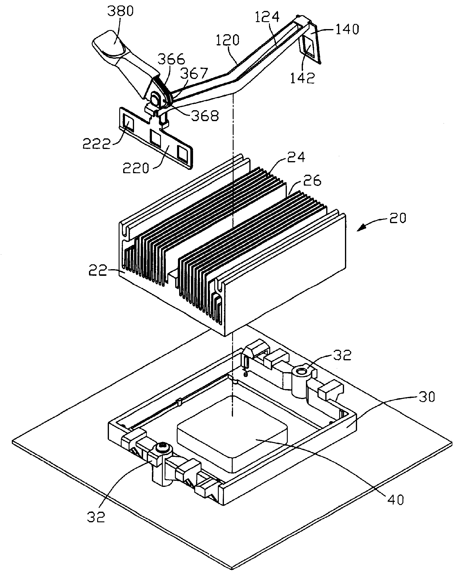
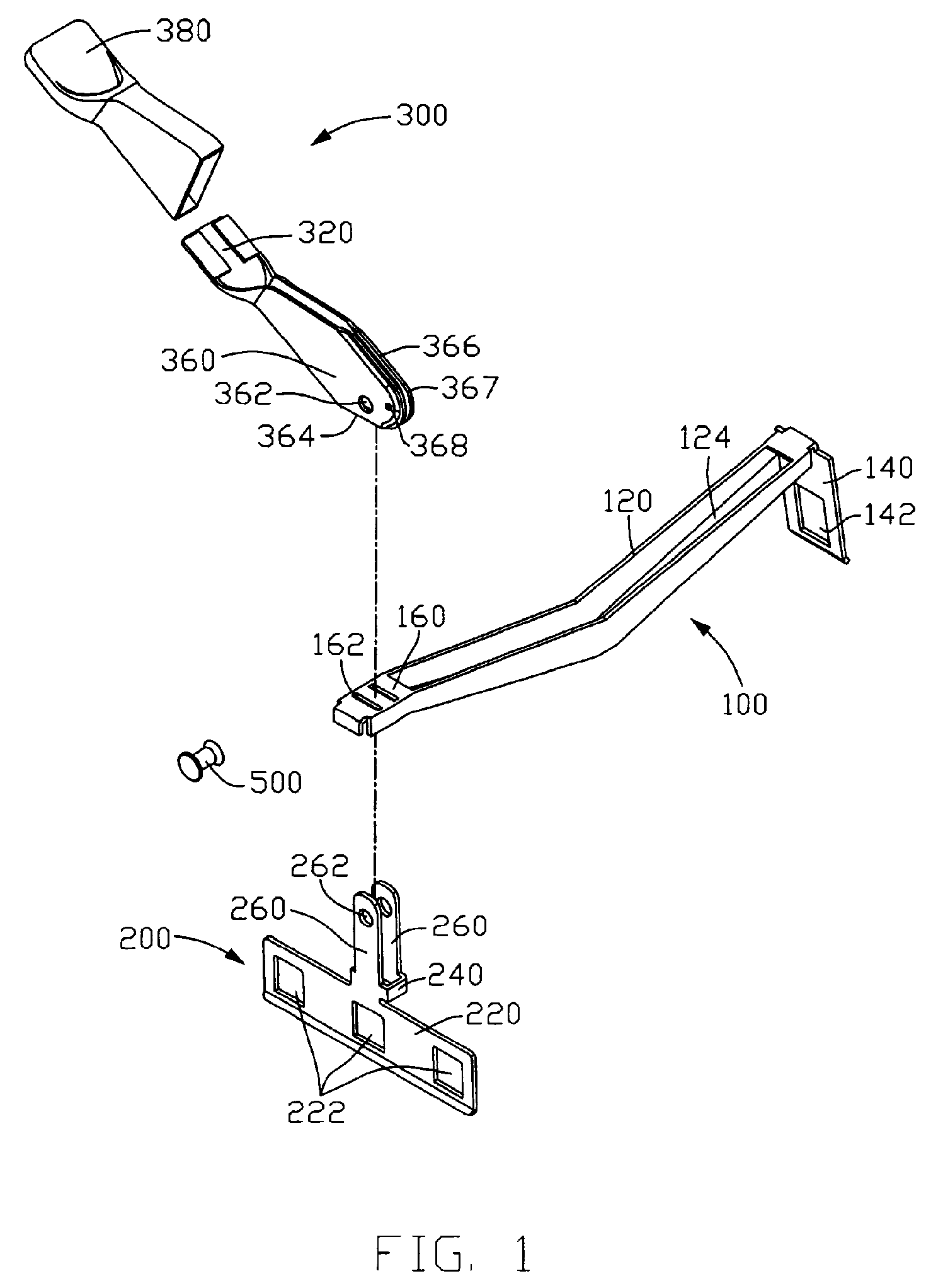
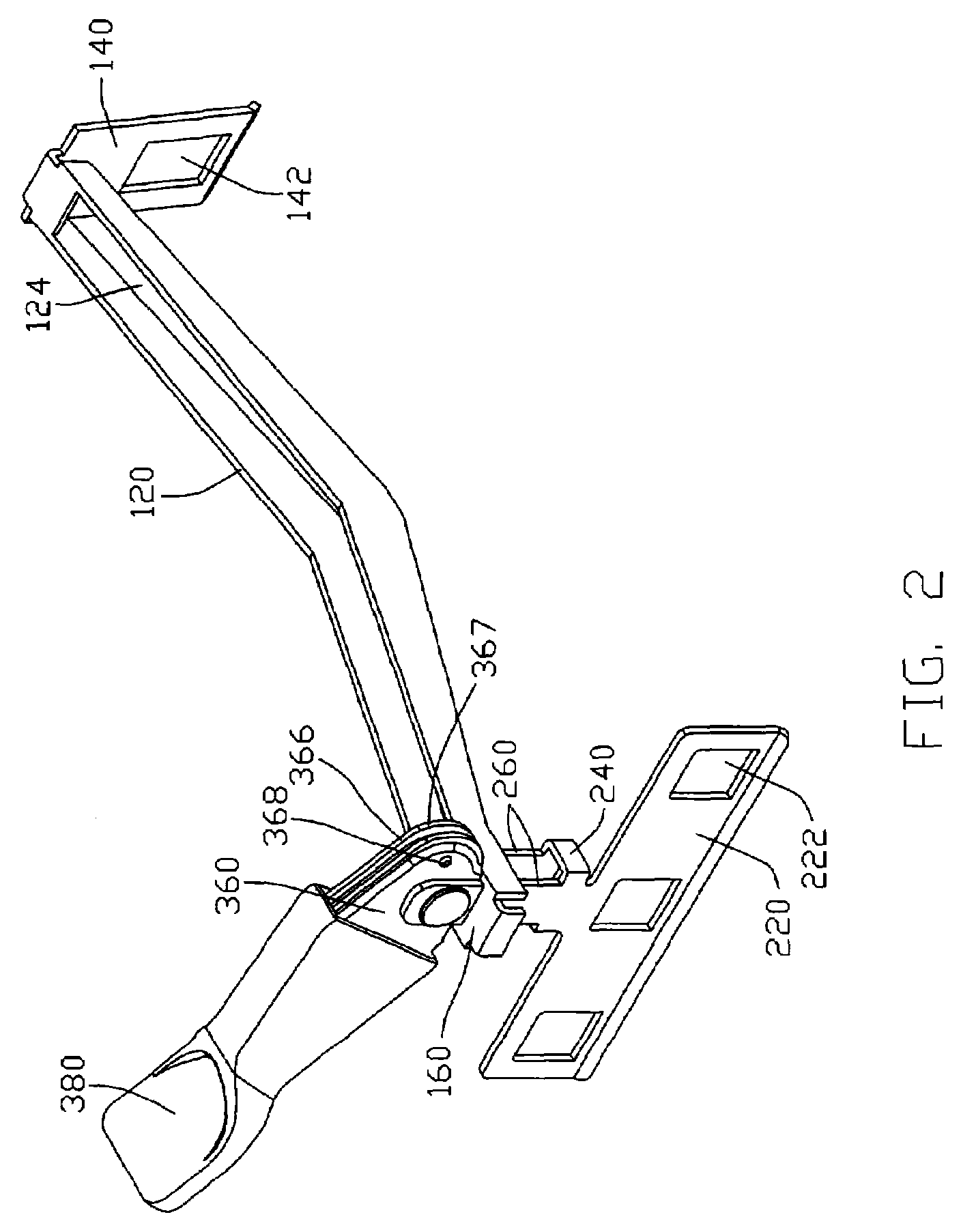
[0015]Referring to FIGS. 1-2, a heat sink fastener (not labeled) in accordance with a preferred embodiment of the invention comprises a main body 100, a piercing body 200, and an operating member 300.

[0016]The main body 100 comprises an elongated pressing part 120, a latching leg 140 and an engaging part 160. The latching leg 140 extends downwardly and outwardly, forming a free end of the pressing part 120, and defines an opening 142 therein. The engaging part 160 extends horizontally from an opposite end of the pressing part 120, and defines two separate engaging slots 162 therein. One slot 162 is located adjacent to the pressing part 120. The pressing part 120 between two ends thereof is provided with an elongated groove 124 for saving material.

[0017]The piercing body 200 comprises a vertical piercing part and a latching part 220 below the piercing part. The piercing part comprises two piercing plates 260 which are separate from and parallel to each other and a bottom thereof conn...


PUM


Abstract

A heat sink fastener includes a main body, a piercing body and an operating member. The main body has a pressing part for pressing a heat sink toward a heat-generating component. An engaging part and a latching leg are disposed at opposite ends of the main body. The piercing body includes a piercing part piercing through the engaging part, and a latching part below the piercing part. The operating member includes a cam pivotally connected to the piercing part and rotatable between locked and unlocked positions. At the locked position, a protrusion formed on the cam abuts a lateral edge of the piercing part to prevent the operating member from spontaneously rotating back to the unlocked position. A bent flange is formed at a periphery of the cam and engages with the engaging part.

Description

FIELD OF THE INVENTION[0001]The present invention relates generally to a heat sink fastener, and more particularly to a heat sink fastener for securing a heat sink to an electronic heat-generating component to remove heat from the heat-generating component.DESCRIPTION OF RELATED ART[0002]Heat sinks are usually used to remove heat from electronic heat-generating components, such as central processing units (CPUs) and the like, to keep the components at stable operation temperatures. A typical heat sink comprises a base for contacting a heat-generating component to absorb the heat of the heat-generating component and a plurality of fins extending from the base for dissipating the heat to ambient air.[0003]To secure the heat sink to the heat-generating component, a fastener is required. A current fastener is disclosed in US Patent Application Publication No. 2005 / 0144764A1. The fastener comprises a pressing member, an engaging member and a handle. The pressing member comprises an elong...

Claims


Application Information

Patent Timeline
Patent Type & Authority Patents(United States)
IPC IPC(8): H05K7/20H01L23/36
CPCH01L23/4093H01L2924/0002H01L2924/00
Inventor LU, CUI-JUNFENG, JIN-SONG
Owner HON HAI PRECISION IND CO LTD
Why Eureka
Try Eureka