
Method and apparatus for interference suppression with efficient matrix inversion in a DS-CDMA system

Active Publication Date: 2008-09-30
III HLDG 1
View PDF151 Cites 42 Cited by
  • Summary
  • Abstract
  • Description
  • Claims
  • Application Information

AI Technical Summary

Benefits of technology

[0010]The present invention is directed to addressing these and other problems and disadvantages of the prior art. According to an embodiment of the present invention, a method and apparatus for canceling interfering signals in connection with a spread spectrum communication system are provided. According to another embodiment of the present invention, an interference matrix is formed having more than two interference vectors related to a symbol of a signal path channel of interest. Accordingly, the present invention can be applied to communication systems that support channels having symbols of different lengths. In accordance with a further embodiment of the present invention, a method and apparatus for efficiently inverting a matrix in connection with interference cancellation are provided.
[0012]In accordance with another embodiment of the present invention, a method and apparatus for efficiently inverting a matrix, such as a matrix produced by performing mathematical operations on an interference matrix for use in connection with an interference cancellation system, is provided. In particular, matrix inversion may be performed using a pseudo inverse in connection with a matrix that is less than full rank. In particular, the basis can be orthogonalized, without requiring a normalization step, resulting in a trivial matrix inversion and computation.

Problems solved by technology

When a demodulation processor is tracking a particular signal path, signal paths associated with other transmitters appear to that processor as noise.
For example, direct sequence code division multiple access (DS-CDMA) communication systems are subject to interference from other DS-CDMA signal sources resulting in signal degradation.
This has a deleterious effect on the acquisition, tracking and demodulation of received signals of interest.
A system of this type is often described as being interference limited, since strongly interfering signals may create an upper bound on system performance.
However, a DS-CDMA receiver is still subject to two forms of multiple access interference on the forward link.
In particular, such signals can cause interference because the orthogonality of the Walsh covering codes is lost whenever a time offset exists between two codes.
Cross-channel interference occurs when a combination of transmissions from more than one base station sector or base station are received at the RF front-end simultaneously.
This manifests itself as cross-correlation interference between signals originating from different base station sectors.
However, such prior art systems have been incapable of handling communication systems supporting symbols of different lengths.
For example, such interference cancellation systems are unable to cancel interference from signal paths in which the interference consists of symbols having lengths that are less than half the length of symbols contained in a desired signal path, because the interference matrix formed using left and right overlapping interference reference vectors cannot span the longer symbol of interest.
Accordingly, such systems cannot be applied to recent spread spectrum communication systems, such as CDMA 2000 that support supplemental (short) Walsh covering codes.
Therefore, such methods introduce computationally expensive and unnecessary steps.
Accordingly, prior art interference cancellation systems requiring matrix inversion computations have been computationally inefficient.

Method used


Image

  • Method and apparatus for interference suppression with efficient matrix inversion in a DS-CDMA system
  • Method and apparatus for interference suppression with efficient matrix inversion in a DS-CDMA system
  • Method and apparatus for interference suppression with efficient matrix inversion in a DS-CDMA system

Examples


Embodiment Construction

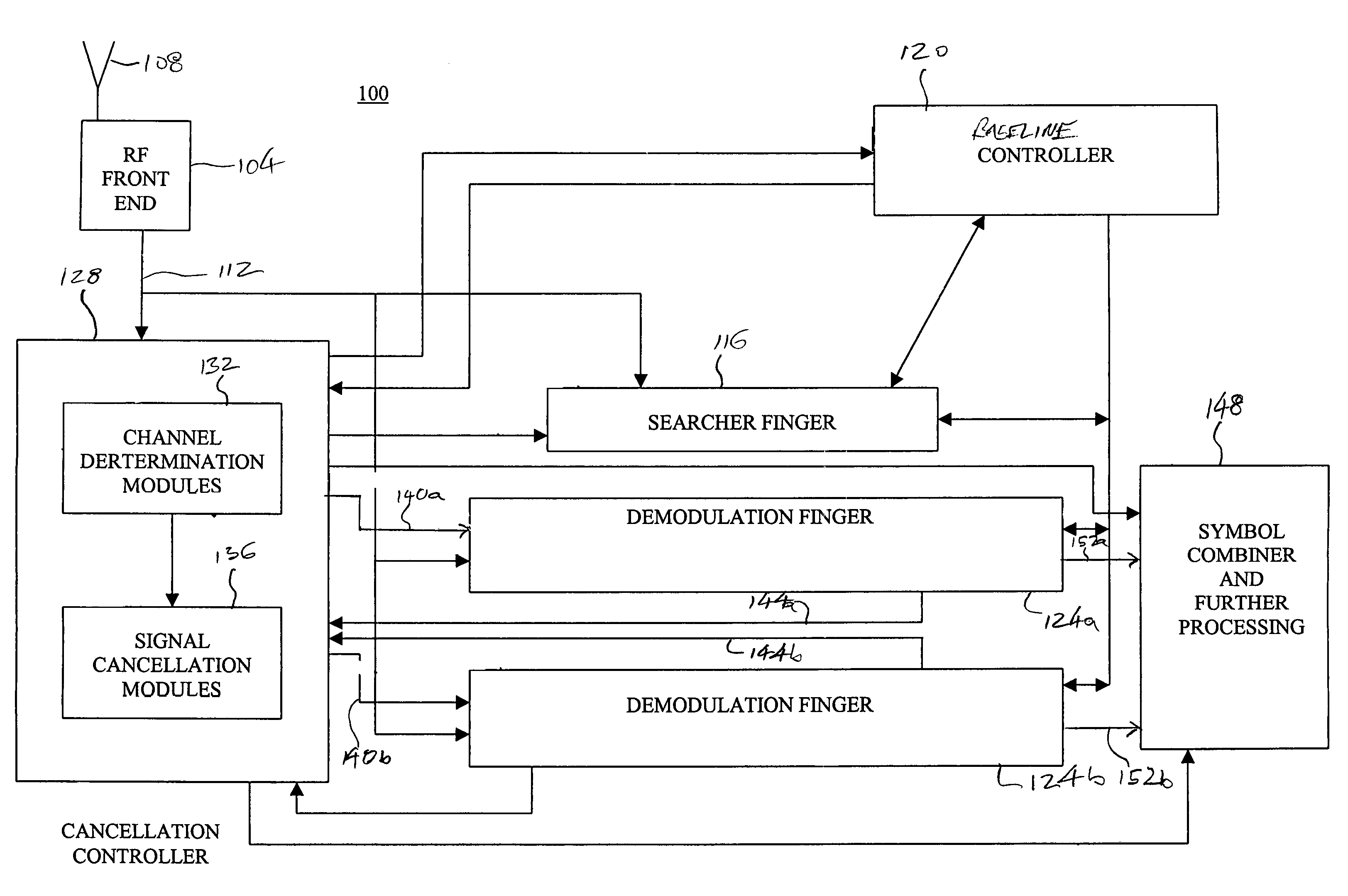
[0022]A direct sequence code division multiple access (DS-CDMA) communication system includes a plurality of base stations and mobile stations. With reference now to FIG. 1, an interference cancellation enabled receiver 100 in accordance with an embodiment of the present invention is illustrated. As depicted in FIG. 1, signals are provided to a radio frequency front end 104 by an antenna 108. In a typical environment, a number of different signals, for example, signals produced by different base stations, different sectors of a base station, or multipath or reflected versions of the signals can be received at the radio frequency front end 104. As can be appreciated by one of skill in the art, signals from different base stations or different sectors of a base station are typically identified by an associated path number or pseudo-random number (PN) offset, which identifies the base station or base station and sector according to the time offset of the signal path. Multipath versions...


PUM


Abstract

The present invention is directed to signal cancellation in spread spectrum communication systems. In particular, the present invention provides method and apparatus for selectively canceling interfering signals, even where symbols to be canceled do not align with symbols associated with a desired signal path. Furthermore, the interference cancellation provided by embodiments of the present invention is capable of functioning to remove interference associated with channels utilizing a symbol length that is different than the symbol length of a desired signal path. In accordance with a further embodiment of the present invention, method and apparatus for efficiently calculating projections to enable signal cancellation are provided.

Description

CROSS-REFERENCE TO RELATED APPLICATIONS[0001]This application claims the benefit of U.S. Provisional Patent Application No. 60 / 418,181, filed Oct. 15, 2002, and U.S. Provisional Patent Application No. 60 / 418,187, filed Oct. 15, 2002, the entire disclosures of which are incorporated herein by reference.FIELD OF THE INVENTION[0002]The present invention relates generally to interference cancellation in communication systems, and more particularly to the construction of an interference matrix as part of an interference cancellation method incorporated into a spread spectrum receiver apparatus. The present invention also relates to matrix inversion and an efficient method for the determination of active channels for cancellation purposes.BACKGROUND OF THE INVENTION[0003]Wireless communication systems should provide for a large number of secure (or private) communication channels within their allotted frequency space. In order to achieve these goals, spread spectrum systems have been deve...

Claims


Application Information

Patent Timeline
IPC IPC(8): H04L27/00H03D1/04H04B1/10H04B1/707H04L
CPCH04B1/71052H04B1/7107H04B1/712H04B1/7117
Inventor OLSON, ERIC S.NARAYAN, ANAND P.JAIN, PRASHANTTHOMAS, JOHN K.
Owner III HLDG 1
Learn More