Electroluminescent vehicle license plate frame for displaying advertisement and associated method

a license plate frame and electric technology, applied in the direction of advertising, display means, instruments, etc., to achieve the effect of effectively attaching the frame to the vehicle and preventing premature separation

Inactive Publication Date: 2008-10-07
COMBS DAVID M
View PDF7 Cites 20 Cited by
  • Summary
  • Abstract
  • Description
  • Claims
  • Application Information

AI Technical Summary

Benefits of technology

[0011]The invention, an upgraded illuminated license plate frame, has a thinner design due to the method of recessing strip lighting that is placed in the back side of the license plate frame; the strip lighting is powered by a direct current inverter that is connected to a direct current power source. This allows you to add text for advertisement or even a design cut, machined, or molded through various types of materials the license plate frame is composed of, and light will illuminate through the area. It also allows for a wider variety of color depending on the colored film that is laid over the strip lighting. This also allows a wide variety of text fonts that can be cut, milled, stamped or molded though the license plate frame during its production. The text and design can be placed almost anywhere along the top, sides or bottom of the front of the license plate frame and will not change the thickness of the license plate frame.
[0012]Accordingly several objects and advantages of the invention are to provide an improved illuminated license plate frame, to provide increased visual cosmetic appeal, to provide a wider variety of color that can be illuminated through the text or design, to provide a wider variety of illuminated text advertisement font's and to also provide a thinner design of a motor vehicle accessory. Still further objects and advantages will become apparent from a study of the following description and the accompanying drawings.
[0016]The strip lighting is stacked on top of the color tinted transparent member so that the strip lighting effectively illuminates through the surface indicia and the design indicia respectively. The backing plate is statically engaged with the front plate, which is necessary such that the strip lighting advantageously remains fixedly disposed therebetween, and does not prematurely separate therefrom during driving conditions.
[0017]The surface indicia are conveniently located at a lower center portion of the frame. The text indicia effectively pass through the frame to the recessed pocket, which is necessary such that light outwardly illuminates through the frame from the strip lighting. Left and right corners of lower and upper portions of the frame are conveniently provided with mounting holes, which is essential for receiving mounting hardware therethrough and effectively attaching the frame to the vehicle. Such mounting hardware secures the frame to the vehicle and prevents premature separation of the frame from the vehicle during operating conditions.

Problems solved by technology

In view of the foregoing disadvantages inherent in the prior art, it has been observed that there is need for electroluminescent license plate frames that illuminate advertisement surface indicia imprinted along a part of the license plate frames.

Method used


Image

  • Electroluminescent vehicle license plate frame for displaying advertisement and associated method
  • Electroluminescent vehicle license plate frame for displaying advertisement and associated method
  • Electroluminescent vehicle license plate frame for displaying advertisement and associated method

Examples


embodiment 1

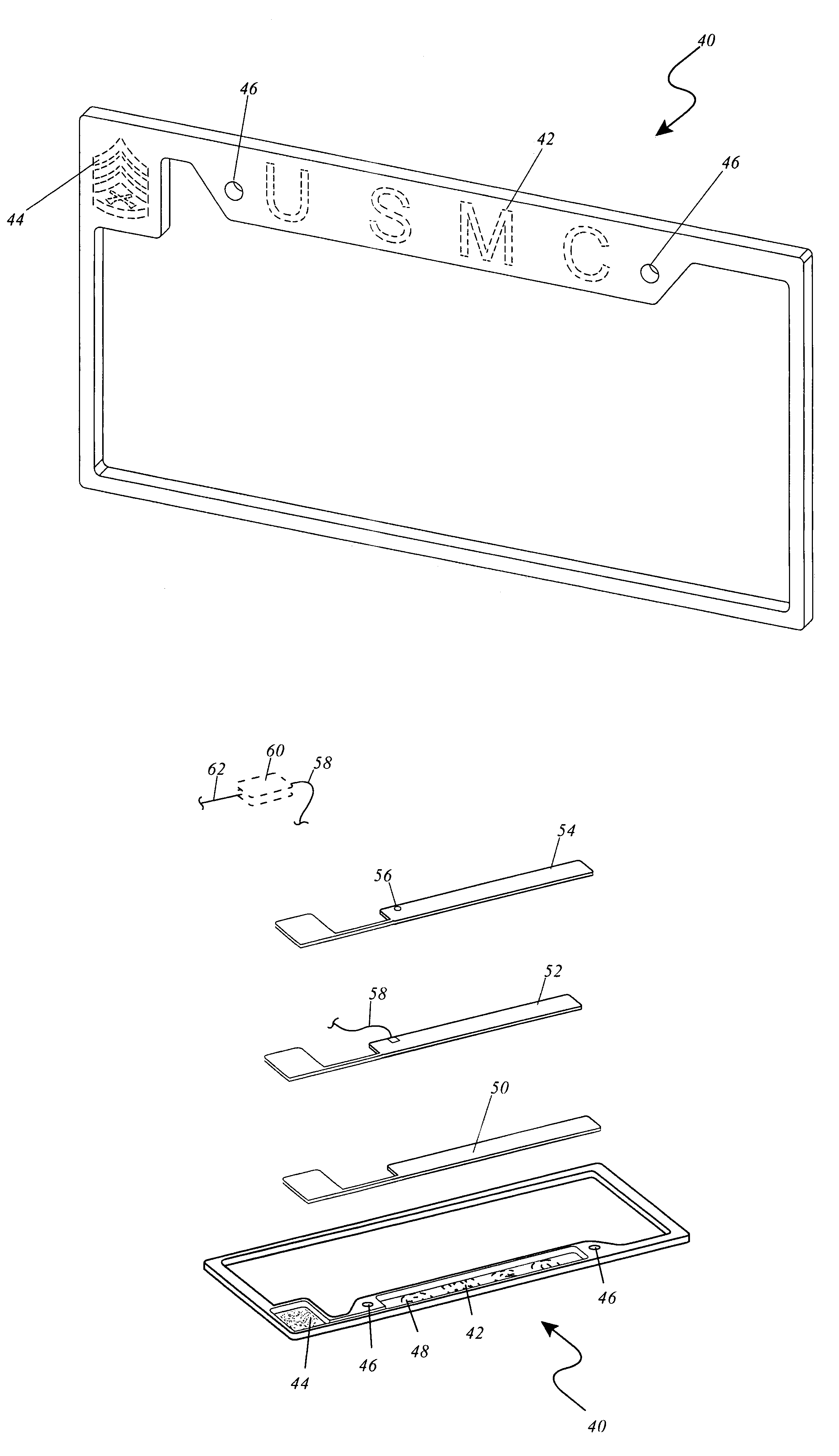
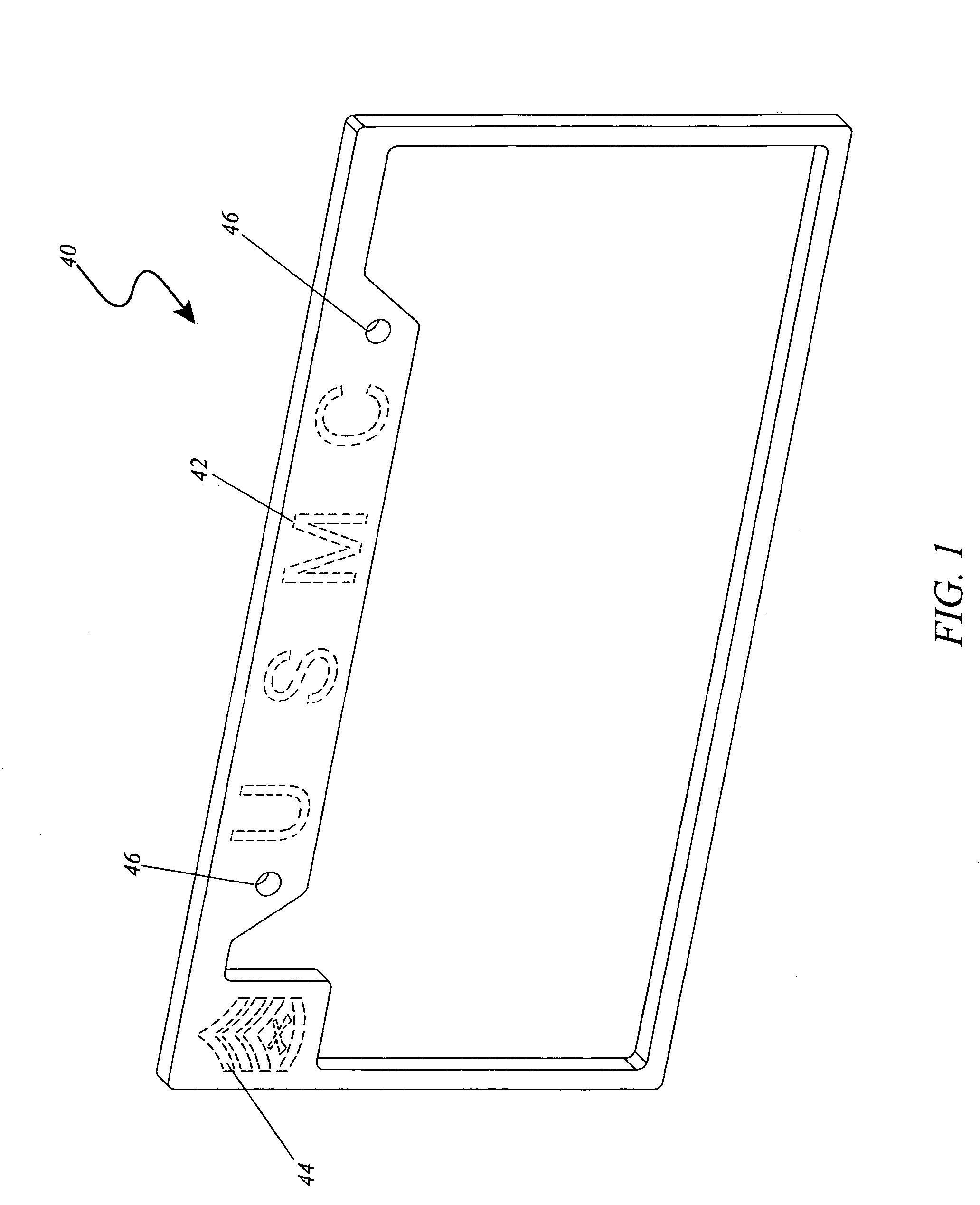
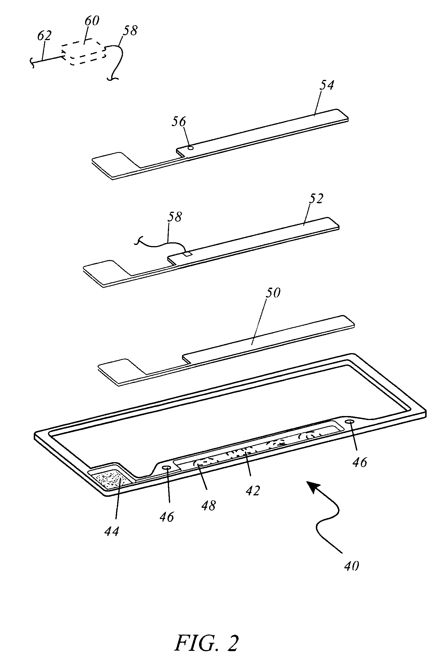
[0055]FIG. 1 is a perspective view taken from the users front-side of the electroluminescent license plate frame (40) constructed in accordance with the invention. The upper center portion of the frame has an area for text advertisement (42) that goes all the way through the frame to the recessed pocket (not shown in this FIG.) so light can illuminate through the frame from electroluminescent strip lighting (not shown in this FIG.). This can be done by use of a milling machine, CNC machine, or molded through the frame during the production process. USMC is used as an example. The upper left portion of the frame is an area for a design (44) that goes all the way through the frame to the recessed pocket (not shown in this FIG.) so light can illuminate through the frame from electroluminescent strip lighting (not shown in this FIG.) This can be done by use of a milling machine, CNC machine, or molded through the frame during the production process. A military rank insignia is used as a...

embodiment 2

[0061]FIG. 7 is a perspective view taken from the users front-side of the electroluminescent license plate frame (40) constructed in accordance with the invention. The upper center portion of the frame has an area for text advertisement (42) that goes all the way through the frame to the recessed pocket (not shown in this FIG.) so light can illuminate through the frame from electroluminescent strip lighting (not shown in this FIG.). USMC is used as an example. The upper right portion of the frame is an area for a design (44) that goes all the way through the frame to the recessed pocket (not shown in this FIG.) so light can illuminate through the frame from electroluminescent strip lighting (not shown in this FIG.). A military rank insignia is used as an example. Both of the electroluminescent lighting strips receive power from a direct current inverter through lead wires (not shown in this FIG.). The upper portion to the right and to the left of the text advertisement (42) are moun...

embodiment 3

[0065]FIG. 11 is a perspective view taken from the users front-side of the electroluminescent license plate frame (40) constructed in accordance with the invention. The lower center portion of the frame has an area for text advertisement (42) that goes all the way through the frame to the recessed pocket (not shown in this FIG.) so light can illuminate through the frame from electroluminescent strip lighting (not shown in this FIG.). USMC is used as an example. The lower left portion of the frame is an area for a design (44) that goes all the way through the frame to the recessed pocket (not shown in this FIG.) so light can illuminate through the frame from electroluminescent strip lighting (not shown in this FIG.). A military rank insignia is used as an example. Both of the electroluminescent lighting strips receive power from a direct current inverter through lead wires (not shown in this FIG.). The lower portion of the frame to the right and to the left of the text advertisement ...


PUM


Abstract

A license plate frame design for providing a thin visually appealing motor vehicle accessory that illuminates advertising text and or a design comprises recessed strip lighting illuminating through recessed color tinted transparent material and through the said advertising test and or said design held or sealed into place by means of a backing plate with a direct current inverter attached by means of lead wires to said motor vehicles controllable direct current power source and to said strip lighting by means of lead wires. Providing the motor vehicle operator to transmit direct current from said motor vehicle when desired, to the said license plate frame to add visual appeal by illuminating their said advertisement and or said design. Thus a very thin and visually appealing motor vehicle accessory is provided.

Description

RELATED APPLICATIONS[0001]The present invention was first described in U.S. Provisional Patent No. 60 / 758,032 filed on Jan. 11, 2006.FIELD OF THE INVENTION[0002]This invention relates to license plate frames for motor vehicles, and more particularly to an electroluminescent license plate frame that illuminates advertisement indicia imprinted along a front portion of the license plate frame.BACKGROUND OF THE INVENTION[0003]License plate frames with lighting are usually not appealing to a motor vehicle enthusiast because of the type of lighting system most often used called LED's. Using LED's on license plate frames can often cause a bulky awkward appearance due to the design of the LED and its circuit required to run them. This also limits the variety of color to mainly a red, blue, green, or white. Visual cosmetic appeal, design and usefulness of a motor vehicle accessory are really what determine whether a motor vehicle owner desires to add an accessory to their vehicle. Other form...

Claims


Application Information

Patent Timeline
Patent Type & Authority Patents(United States)
IPC IPC(8): G09F7/00G09F13/08
CPCB60R13/10G09F13/22G09F21/04
Inventor COMBS, DAVID M.
Owner COMBS DAVID M
Why Eureka
Try Eureka