Face seal with constriction ring

a sealing ring and sealing plate technology, applied in the field of shaft seals, can solve the problems of increasing frictional hysteria, loud seal squealing, squeaking, chirping or moaning noise, annoying vibration of the sealing ring, etc., and achieve the effect of preventing the impeller from overheating

Active Publication Date: 2008-10-07
FREUDENBERG NOK GEN PARTNERSHIP
View PDF8 Cites 13 Cited by
  • Summary
  • Abstract
  • Description
  • Claims
  • Application Information

AI Technical Summary

Benefits of technology

[0002]A mechanical face seal, which may be employed, for example, in a dishwasher pump, may include a stationary seal head assembly that mates with, and seals against, a rotating seal seat assembly. Typically, the seal seat assembly mounts to an impeller that is driven via a shaft by a motor. It is common for the impeller to be made of a plastic material. Such a conventional face seal assembly performs very well at sealing out water, and prevents the impeller from overheating because the water adjacent to the seal absorbs frictional heat generated by the seal. A rubber bellows or boot of the seal head assembly provides an axially flexible sealing membrane between the seal ring and the pump housing. A spring biases the seal ring against the seal seat. A concern with these conventional face seals is that a vibrating seal ring can emit annoying, loud seal squealing, squeaking, ringing, chirping, or moaning noises, especially sealing water-based fluids at elevated temperatures or under marginal lubrication.
[0003]Thus, it is desirable to have a face seal for a rotating shaft that will adequately seal water, and can also significantly reduce the vibration of the seal ring to prevent annoying, loud noises from being generated.
[0004]Accordingly, the present disclosure provides the rubber bellows or boot-type mechanical face seal with a constriction ring that constricts the normal outward bulging of the flex section of the rubber boot as it folds and tries to roll forward over itself during axial deflection. This constriction causes increased frictional hysteresis during compression and decompression of the boot flex section. The increased hysteresis, defined as the difference between the load / deflection curve resulting from axially compressing the seal from its free height to near its solid height and the load / deflection curve resulting from releasing the seal from near its solid height to its free height, increases the dampening capacity of the seal design four to six fold, or more, compared to conventional non-constricted designs. The increased dampening action suppresses high frequency frictional stick-slip vibrations between the rotating and stationary rubbing seal components, thus suppressing high frequency vibrations of the seal ring to prevent annoying noise generation.

Problems solved by technology

A concern with these conventional face seals is that a vibrating seal ring can emit annoying, loud seal squealing, squeaking, ringing, chirping, or moaning noises, especially sealing water-based fluids at elevated temperatures or under marginal lubrication.
This constriction causes increased frictional hysteresis during compression and decompression of the boot flex section.

Method used


Image

  • Face seal with constriction ring
  • Face seal with constriction ring
  • Face seal with constriction ring

Examples


Embodiment Construction

[0014]The following description of the preferred embodiment(s) is merely exemplary in nature and is in no way intended to limit the disclosure, its application, or uses.

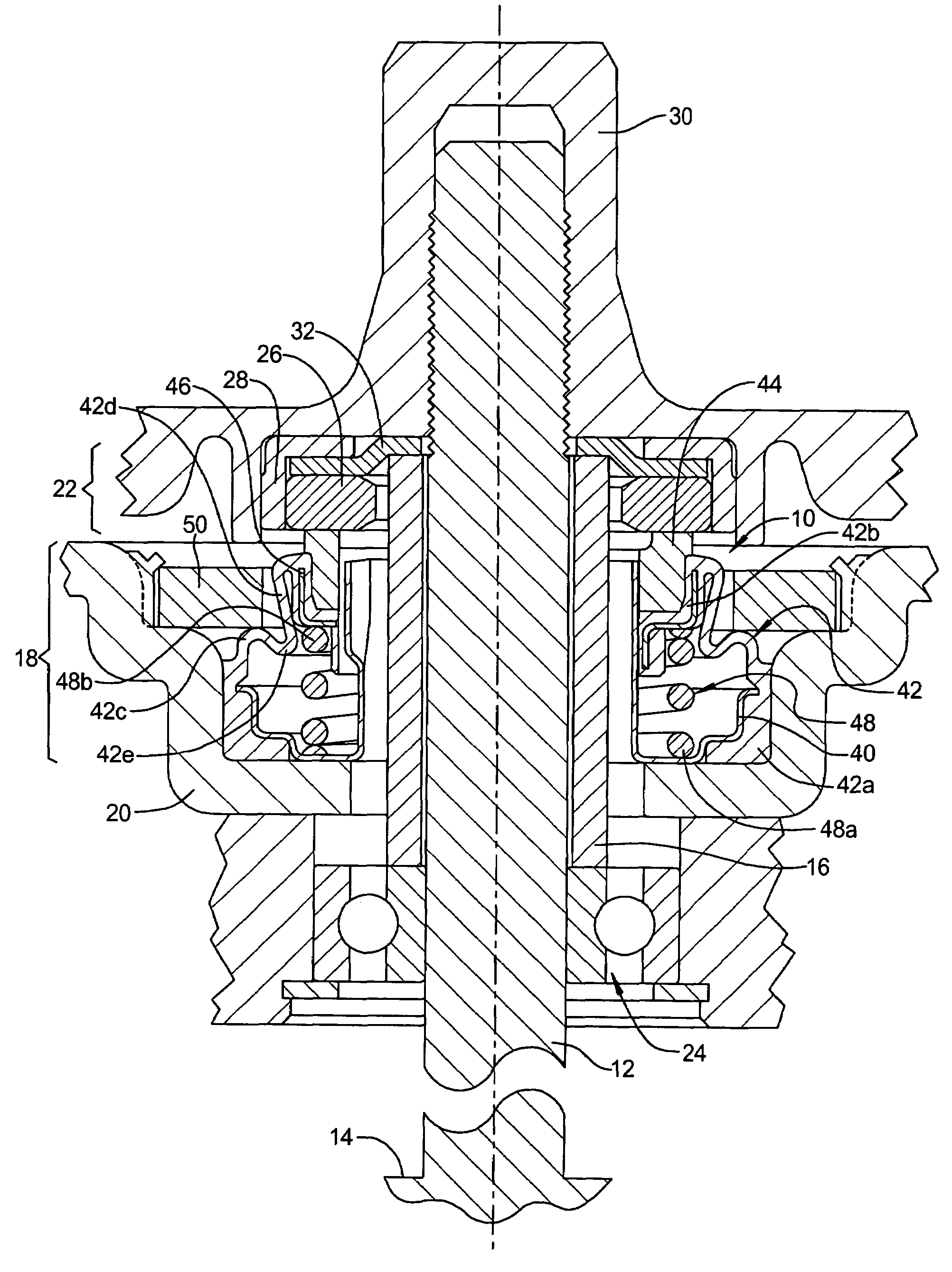
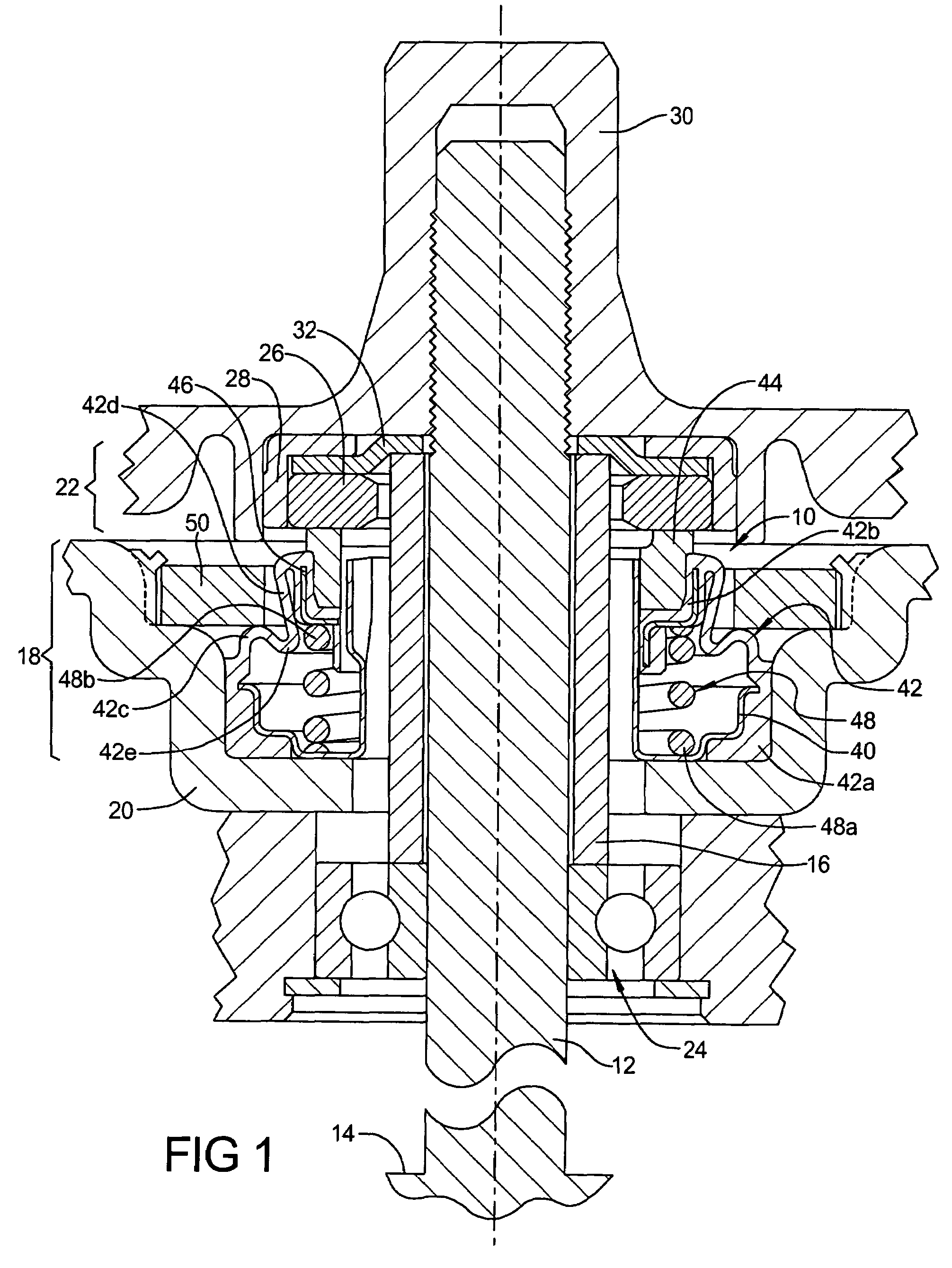
[0015]With reference to FIG. 1, a mechanical face seal assembly 10 is mounted about a rotatable shaft 12. The rotatably shaft 12 may be driven by, for example, a pump motor 14 in an automatic dishwasher, although the seal assembly 10 may be employed in other types of sealing applications for a rotatable shaft 12. The shaft 12 includes a shaft sleeve 16 mounted thereon. As an alternative to a shaft sleeve 16, the shaft 12 may have a shoulder formed thereon.

[0016]The seal assembly 10 includes a seal head assembly 18, mounted stationary relative to a pump housing 20, and a seal seat assembly 22, rotationally fixed to the shaft 12. A bearing 24 mounts to the shaft 12 with an inner race thereof abutting the shaft sleeve 16. The seal seat assembly 22 includes a seal seat 26 which abuts against the seal head assembly 18. A ...


PUM


Abstract

A face seal is provided with a constriction ring around a rubber boot that constricts the normal outward bulging of the flex section of the rubber boot as it folds and tries to roll forward over itself during axial deflection. The constriction caused by the constriction ring provides for increased frictional hysteresis during compression and decompression of the boot flex section. This increased hysteresis increases the dampening capacity of the seal design and, therefore, reduces undesired vibrations and seal noise generation.

Description

FIELD OF THE INVENTION[0001]The present disclosure relates in general to shaft seals, and more particularly, to mechanical face seals employed with rotating shafts.BACKGROUND AND SUMMARY OF THE INVENTION[0002]A mechanical face seal, which may be employed, for example, in a dishwasher pump, may include a stationary seal head assembly that mates with, and seals against, a rotating seal seat assembly. Typically, the seal seat assembly mounts to an impeller that is driven via a shaft by a motor. It is common for the impeller to be made of a plastic material. Such a conventional face seal assembly performs very well at sealing out water, and prevents the impeller from overheating because the water adjacent to the seal absorbs frictional heat generated by the seal. A rubber bellows or boot of the seal head assembly provides an axially flexible sealing membrane between the seal ring and the pump housing. A spring biases the seal ring against the seal seat. A concern with these conventional...

Claims


Application Information

Patent Timeline
Patent Type & Authority Patents(United States)
IPC IPC(8): F16J15/34F16J15/38
CPCF16J15/3476F16J15/348F16J15/36
Inventor DAHLHEIMER, JOHN C.
Owner FREUDENBERG NOK GEN PARTNERSHIP
Why Eureka
Try Eureka