
Locator assembly

a technology of locators and assembly lines, applied in the direction of roofs, transportation and packaging, vehicle arrangements, etc., can solve the problem of time-consuming assembly process parts, and achieve the effect of saving assembly line time, reducing assembly time, and more accurate and rapid assembly of front end modules

Inactive Publication Date: 2008-10-07
MAGNA INTERNATIONAL INC
View PDF7 Cites 8 Cited by
  • Summary
  • Abstract
  • Description
  • Claims
  • Application Information

AI Technical Summary

Benefits of technology

The present invention provides a locating pin and a retention clip for aligning and securing the front end module with the body structure. This saves time in the assembly line and allows for faster and more accurate assembly, reducing the time required for assembly. The technical effect of this invention is improved efficiency and accuracy in the assembly process.

Problems solved by technology

Because the rate of production is so high in many cases, this portion of the assembly process is more time consuming than the allotted time allowed for the operation.

Method used


Image

  • Locator assembly
  • Locator assembly
  • Locator assembly

Examples


Embodiment Construction

[0011]The following description of the preferred embodiment(s) is merely exemplary in nature and is in no way intended to limit the invention, its application, or uses.

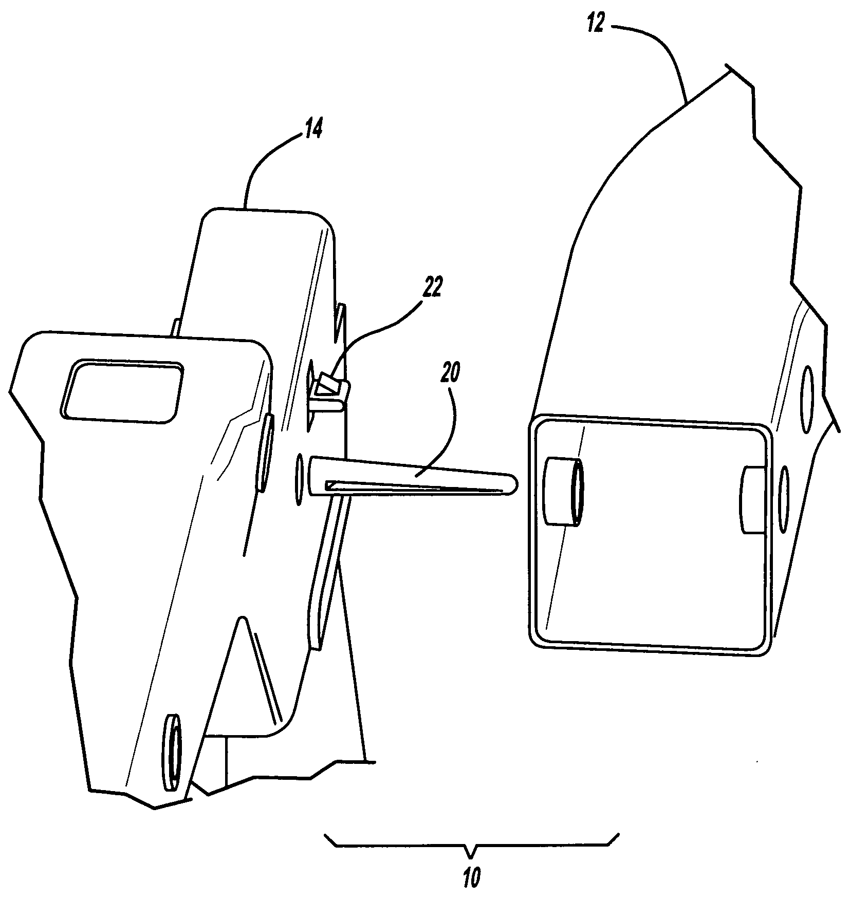
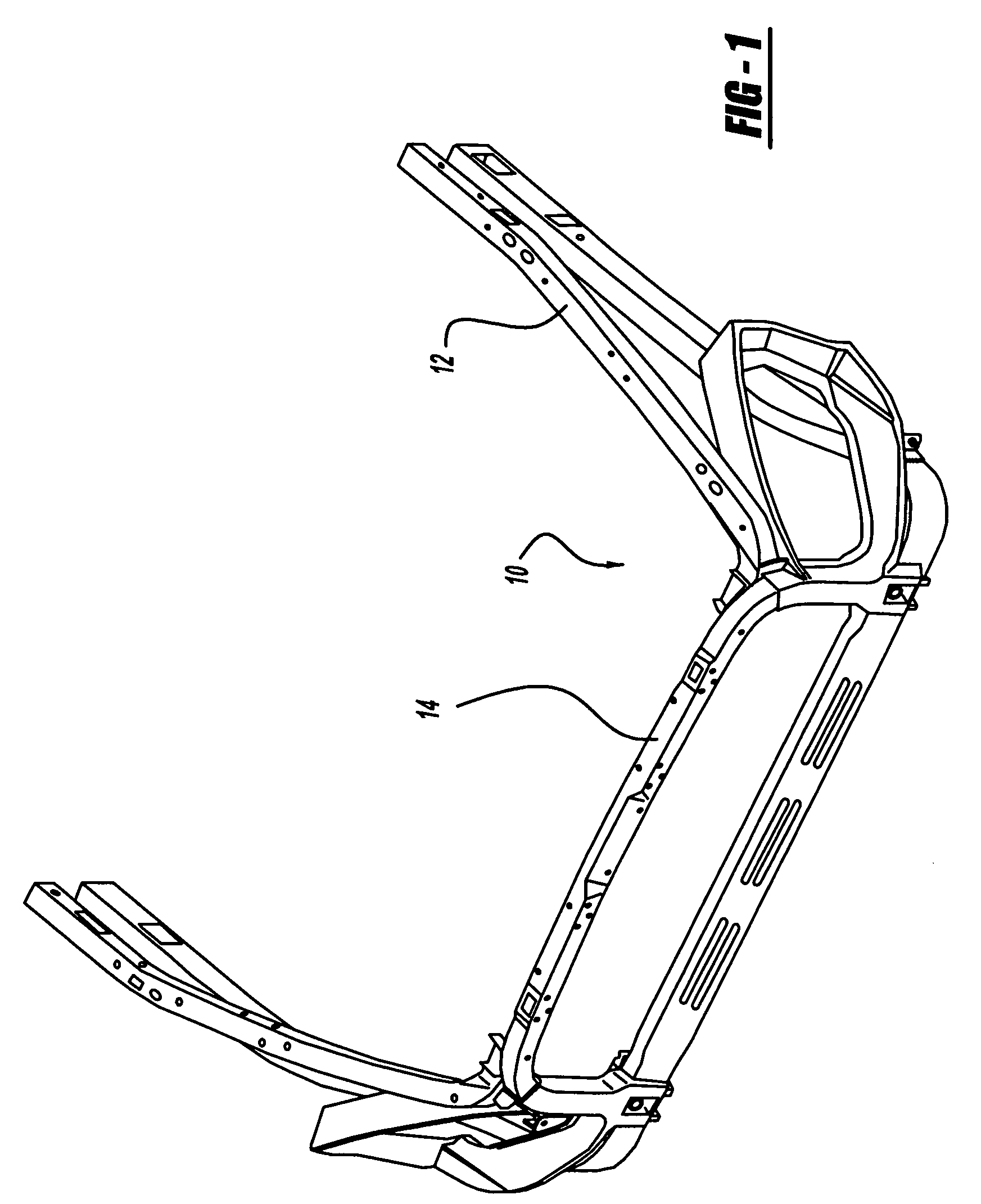
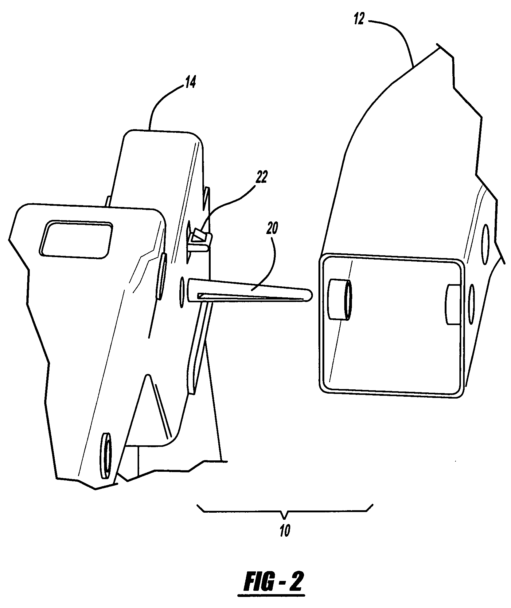
[0012]Referring now to FIGS. 1-3, a locator assembly 10 is generally shown. The locator assembly is used for locating and affixing the body structure 12 to the front end module 14. As shown in FIG. 1, front end module 14 includes various fixtures attached and is assembled in an assembly line to the body structure 12. Typically, an operator uses a lift-assist type arrangement to align a number of mounting holes 16 and 18 between the front end module and the body structure. Then the module is attached via holes as they are kept aligned until.

[0013]In the present invention, the locator assembly includes a locator pin 20 and a retention clip 22. As shown in FIG. 3, the front end module connected locator pin 20 is elongated and inserted through a location hole 24. This brings the body 12 and module 14 in alignment. As the ...


PUM

PropertyMeasurementUnit
timeaaaaaaaaaa

Abstract

In accordance with the present invention, there is provided a locating pin and a retention clip. The locating pin and the retention clip allow alignment of the front end module with the body structure and the retention clip secures the two assemblies in place which allows alignment of fastener holes. This conserves time in the assembly line and allows more accurate and rapid assembly of the front end module on the body structure reducing the time necessary for assembly.

Description

CROSS-REFERENCE TO RELATED APPLICATIONS[0001]This application is a continuation of PCT / US2006 / 038630 filed Sep. 29, 2006, which claims the benefit of U.S. Provisional Application No. 60 / 722,273 filed Sep. 30, 2005. The disclosures of the above applications are incorporated herein by reference.TECHNICAL FIELD[0002]The present invention relates to a locator assembly, in more particularly, to a locator assembly for temporarily aligning a front module with a body structure.BACKGROUND OF THE INVENTION[0003]In the automotive industry, one of the assembly steps is the necessity of attaching the front end module having various components onto a body structure. Typically, an assembly person requires a lift-assist to align the components and thereafter fasteners need to be positioned and fastened for securing the assembly of the front end module or other modules to the body structure. Because the rate of production is so high in many cases, this portion of the assembly process is more time co...

Claims


Application Information

Patent Timeline
Patent Type & Authority Patents(United States)
IPC IPC(8): B60R27/00B60R99/00
CPCB62D25/082B62D25/084B62D65/04B62D65/02Y10T29/49895
Inventor KAPADIA, AMEIL A.SCHALTE, GARI M.PILETTE, THOMAS
Owner MAGNA INTERNATIONAL INC
Learn More