Bicycle drive system

a drive system and bicycle technology, applied in the field of bicycles, can solve the problems of complete failure, excessive wear, and poor function, and achieve the effect of reducing the cost of operation

Inactive Publication Date: 2008-10-14
SCRANTON PETER
View PDF18 Cites 41 Cited by
  • Summary
  • Abstract
  • Description
  • Claims
  • Application Information

AI Technical Summary

Problems solved by technology

The disadvantages associated with chain drives are the exposure of the lubricated parts to contamination, causing excessive wear to interfacing parts and causing poor function, to complete failure, of operation.
Another disadvantage is the exposure of the meshing point of the chain and sprocket, leaving it open to debris to be caught between the chain and sprocket rendering the system inoperable.
The position of the rear derailleur makes it susceptible to strikes from obstacles occurred on roads or off-road trails.
The chain can be thrown from the sprocket during operation on harsh road or trail conditions, again rendering it inoperable.
This makes them cumbersome to enclose in order to shield from contamination.
None of these prior art drive shaft systems consider frames designed for rear suspension and the requirements therein.

Method used


Image

  • Bicycle drive system
  • Bicycle drive system
  • Bicycle drive system

Examples


Embodiment Construction

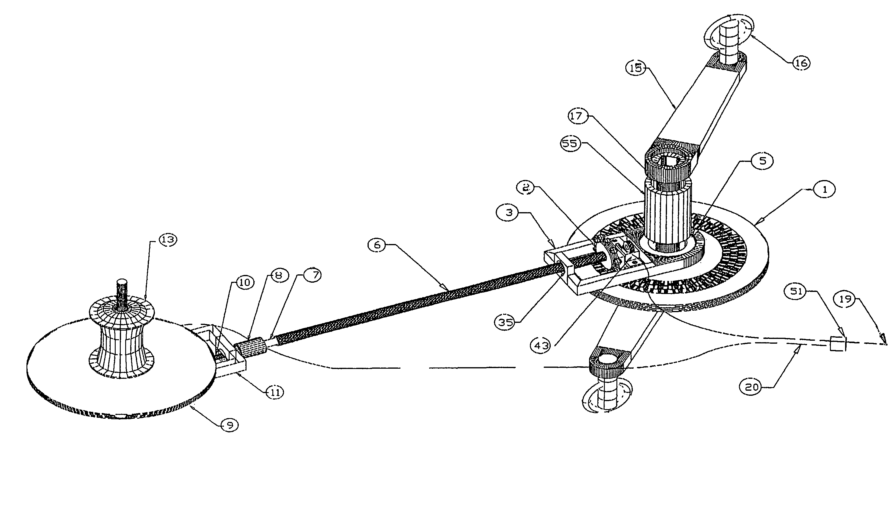
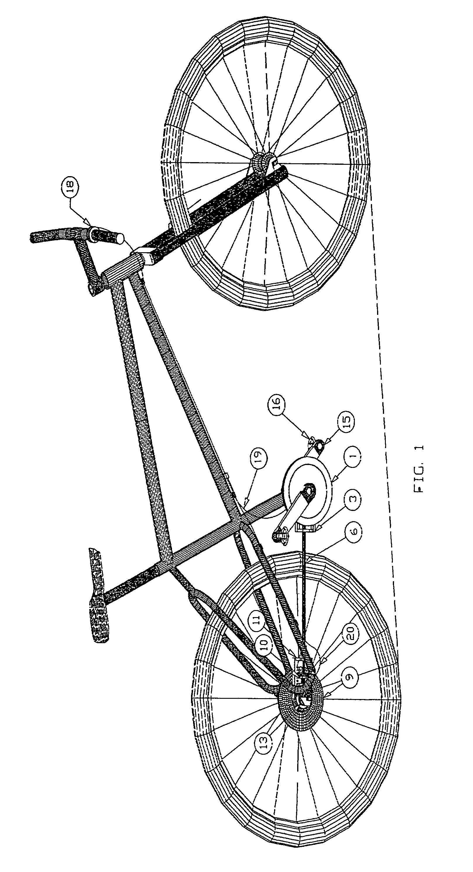
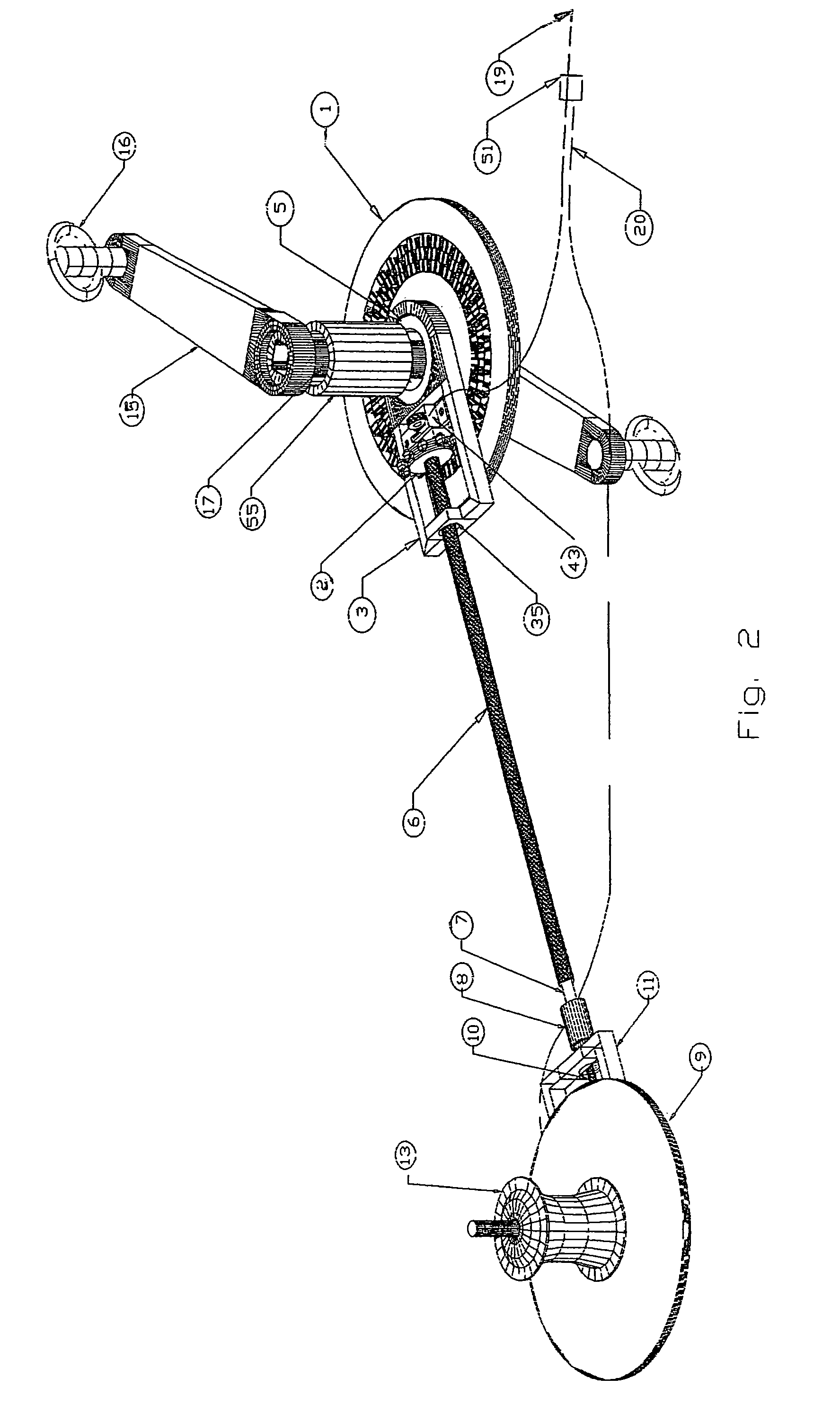
[0017]Embodiments of the present invention are directed to a bicycle drive system. The bicycle drive system includes a front gear face, a rear gear face, a front guide assembly, a rear guide assembly, and a drive shaft. The bicycle drive system is preferably coupled to a rear-suspension frame via a rear hub and a crank spindle. The rear hub preferably includes a conventional freewheel mechanism and the crank spindle is positioned through a frame spindle hole in the frame such that the bicycle drive system operates independently of the frame. This enables the bicycle drive system to operate with independent frame designs.

[0018]The bicycle drive system includes a multitude of gear ratios, each gear ratio corresponding to a gear. Shifting from one gear to another is controlled by a shift controller which is preferably coupled to the bicycle handlebars. In the preferred embodiment, the bicycle drive system includes twelve consecutive gear ratios controlled by a single shift controller. ...


PUM


Abstract

A bicycle drive system includes a front gear face, a rear gear face, a front guide assembly, a rear guide assembly, and a drive shaft coupled to a rear-suspension frame via a rear hub and a crank spindle. The bicycle drive system operates independently of the frame. Shifting from one gear to another is controlled by a shift controller. Each shift of the shift controller shifts both the front and rear guide assemblies at the same time. The shift controller is preferably coupled to the front and rear guide assemblies via a cable system.

Description

FIELD OF THE INVENTION[0001]The present invention relates to bicycles. In particular, the present invention relates to a bicycle drive system.BACKGROUND OF THE INVENTION[0002]Conventional bicycle drive trains utilize a chain drive composed of a chain and sprockets to transfer motion from the pedals to the rear wheel of the bicycle. The disadvantages associated with chain drives are the exposure of the lubricated parts to contamination, causing excessive wear to interfacing parts and causing poor function, to complete failure, of operation. To prevent this requires frequent cleaning.[0003]Another disadvantage is the exposure of the meshing point of the chain and sprocket, leaving it open to debris to be caught between the chain and sprocket rendering the system inoperable. The position of the rear derailleur makes it susceptible to strikes from obstacles occurred on roads or off-road trails. The chain can be thrown from the sprocket during operation on harsh road or trail conditions,...

Claims


Application Information

Patent Timeline
Patent Type & Authority Patents(United States)
IPC IPC(8): F16H3/22
CPCB62M17/00F16H3/366Y10T74/19353Y10T74/1966Y10T74/19358Y10T74/1933
Inventor SCRANTON, PETER
Owner SCRANTON PETER
Why Eureka
Try Eureka