
Robotized laparoscopic system

a robotic system and laparoscopic technology, applied in the field of laparoscopic systems, can solve the problems of system distraction, adversely affecting the outcome of surgery, and increasing the manufacturing cost and system size,

Active Publication Date: 2008-10-14
KOREA ADVANCED INST OF SCI & TECH
View PDF19 Cites 134 Cited by
  • Summary
  • Abstract
  • Description
  • Claims
  • Application Information

AI Technical Summary

Benefits of technology

The system enables precise and efficient surgical site visualization and control, reducing distractions and operational costs by allowing direct surgeon control, minimizing system movement outside the abdominal cavity, and providing equivalent image quality without an assistant, while being applicable to surgeries where pivot formation is impossible.

Problems solved by technology

However, many factors such as difference in the level of expertise frequently undermine accurate and effective communications, i.e., issuing and following commands, between a surgeon and an assistant, and the inaccurate communications may adversely affect outcome of a surgery.
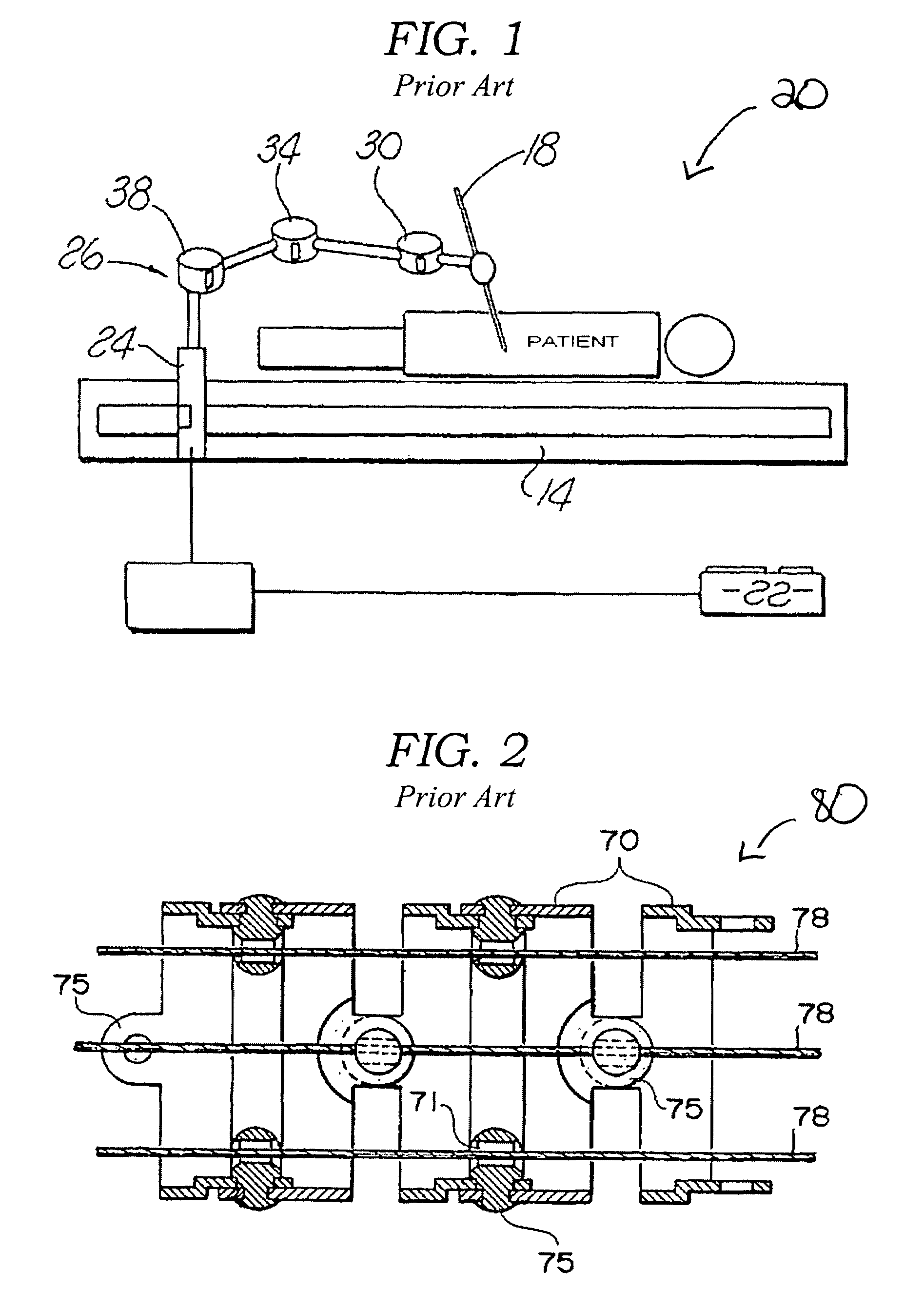
However, the system creates distractions to a surgeon because of a large motion of the robotic arm 26 actuated by multiple joints.
Further, a plurality of actuators 24, 30, 34 and 38 are needed to generate a required motion, which increases manufacturing costs and size of the system.
However, in case of thyroidectomy or sternotomy, formation of a pivot is impossible and this system 20 may not apply to these surgeries.
If the actuators are activated, pulling the wires 78 causes a change in tension of the wires and results in bending of the links 70.
However, the systems disclosed in the above-mentioned patents cannot apply to a laparoscopy.
Because they are designed to inspect human organs through tortuous intestines, an accurate and detailed control of motions is not possible.

Method used


Image

  • Robotized laparoscopic system
  • Robotized laparoscopic system
  • Robotized laparoscopic system

Examples


Embodiment Construction

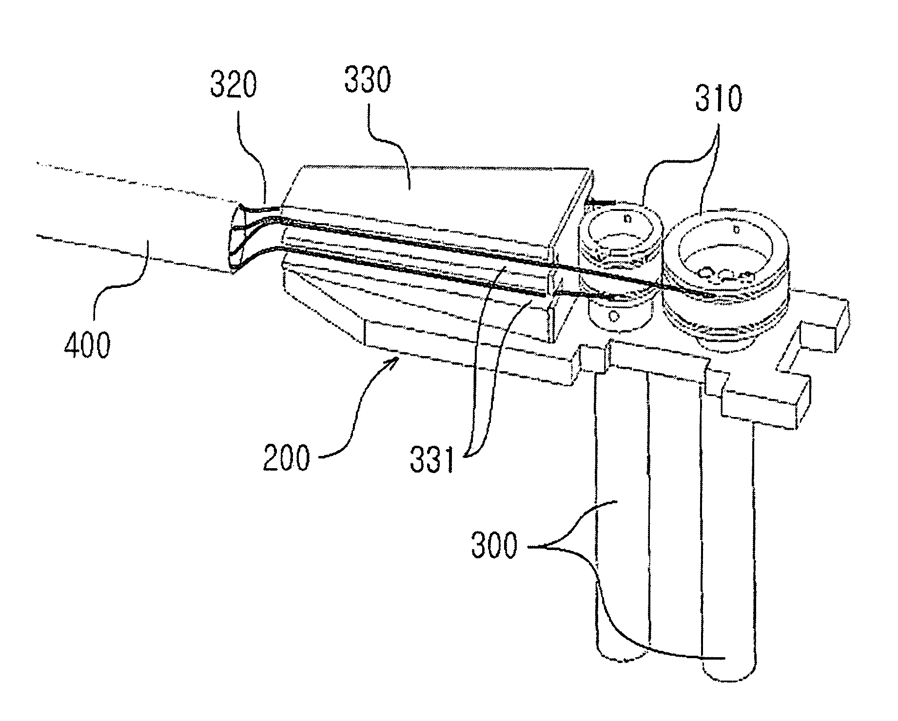
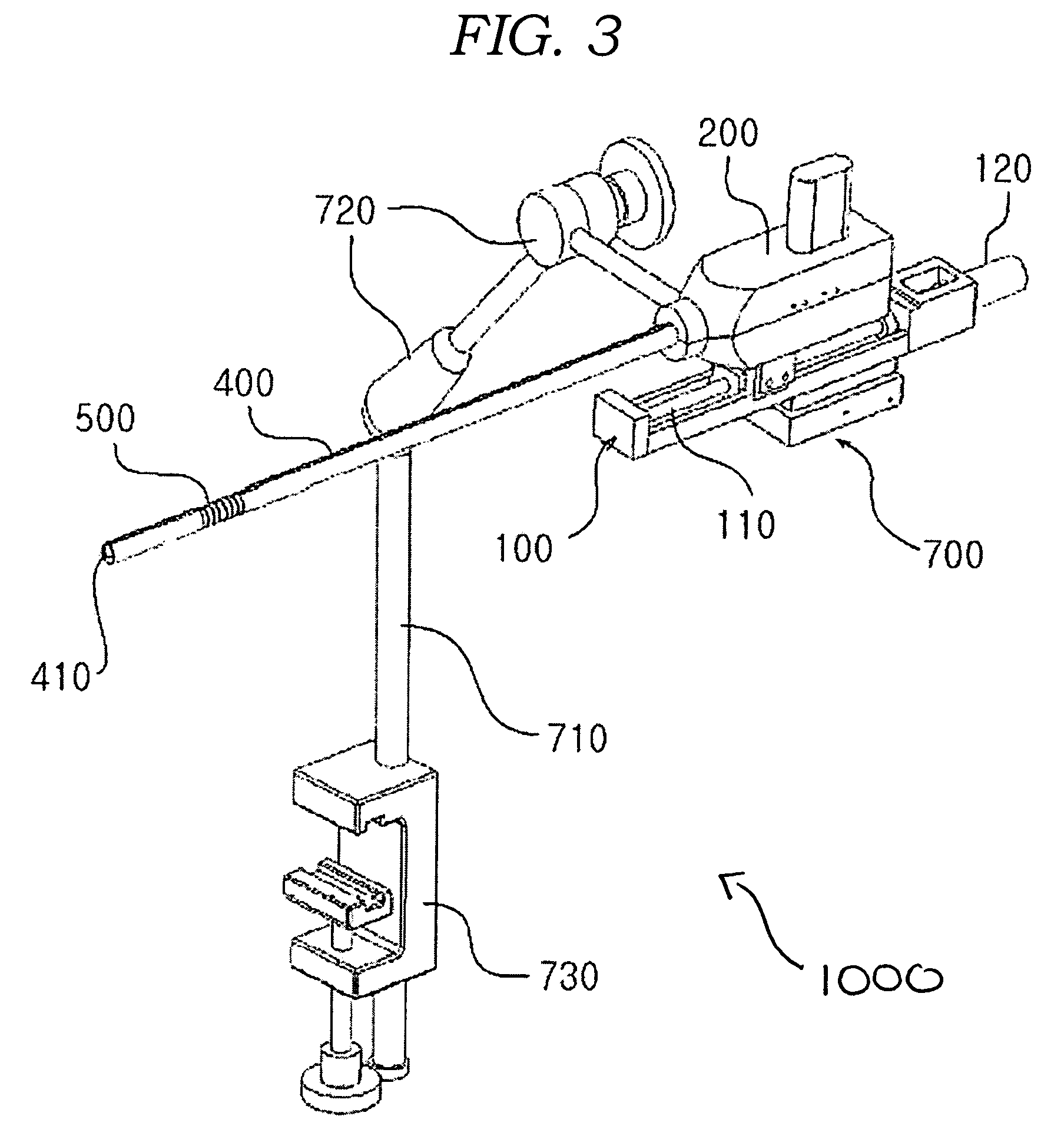
[0025]FIG. 3 shows one embodiment of a robotized laparoscopic system, which is capable of executing a surgeon's commands. A laparoscopic system 1000 includes a guide unit 100, a bending actuator housing 200 and a penetration tube 400. The guide unit 100 supports the bending actuator housing 200 and other portions and is coupled to a support unit 700. The support unit 700 is fixed on an operating table or floor. The support unit 700 includes a fixture 730 that is able to be easily fastened and clamped to the operating table and a support rod 710 that supports the guide unit 100 to maintain its height from the operating table at a certain level. A plurality of joints 720 are coupled to the support rod 710 and spaced apart from each other at a predetermined distance to adjust the position and orientation of the guide unit 100.

[0026]FIG. 4 illustrates in detail the guide unit 100 coupled to the support unit 700. A protrusion 130 is inserted into a groove 701 of the support unit 700, whi...


PUM


Abstract

A robotized laparoscopic system capable of executing commands of an operating surgeon is provided. The laparoscopic system includes a cylindrical tube inserted through an incision. A small-sized camera is attached to one end of the tube to capture the images of the surgical site. A bending portion is adapted to bend the tip of the tube in any direction. A driving unit controls a bending direction and a bending angle of the bending portion. A movement device moves the tube forward or backward in a longitudinal direction. A control unit independently controls the driving unit and the movement device. An input unit receives commands from the surgeon. A conversion unit converts the command input from the surgeon into digital signals and transmits the digital signals to the control unit. A support unit supports the weight of the movement device by being connected to an operating table or the floor.

Description

PRIORITY CLAIM[0001]This application claims under 35 U.S.C. § 119 the benefit of the filing date of Apr. 22, 2004 of Korean Application No. 2004-27949, the entire contents of which are incorporated herein by reference.BACKGROUND[0002]1. Technical Field[0003]The invention generally relates to a laparoscopic system and, more particularly, to a robotized laparoscopic system capable of executing a surgeon's commands.[0004]2. Related Art[0005]A laparoscopic system visualizes a surgical site through a tube inserted through an opening in the abdominal walls. Various surgical instruments such as surgical scalpels, surgical needles, etc. are generally used with a laparoscope. A surgeon in charge of surgery normally operates surgical instruments, whereas an assistant helping a surgeon operates a laparoscope during the surgery. An assistant operates the laparoscope according to commands from a surgeon and communications between a surgeon and an assistant are very important to achieve a success...

Claims


Application Information

Patent Timeline
Patent Type & Authority Patents(United States)
IPC IPC(8): A61B1/00A61B1/005A61B1/313A61B19/00
CPCA61B1/0055A61B1/3132A61B19/2203A61B19/5212A61B2019/2242A61B34/30A61B34/71A61B90/361A47J37/043A47J37/0745A47J37/0754A47J37/0786A47J47/16
Inventor KWON, DONG SOOKO, SEONG YOUNGKIM, JONATHANLEE, YUN JULEE, WOO JUNG
Owner KOREA ADVANCED INST OF SCI & TECH
Learn More