Surgical retractor positioning device

a positioning device and surgical technology, applied in the field of surgical retractor positioning devices, can solve the problems of difficult to minimize the size of the incision, potential trauma, and perform delicate surgery, and achieve the effect of increasing the flexibility of the operating field in the patien

Inactive Publication Date: 2008-10-14
DEPUY SPINE INC (US)
View PDF27 Cites 94 Cited by
  • Summary
  • Abstract
  • Description
  • Claims
  • Application Information

AI Technical Summary

Benefits of technology

[0004]The present invention provides a surgical retractor that includes a retractor positioning device to create a surgical working field in a minimally invasive and flexible manner. In one embodiment, the device can include a frame and an arm connected to the frame. The arm can include a proximal end, a distal end having a distal end axis, and a major axis, wherein the distal end axis is movable relative to the proximal end, whereby the distal end axis can intersect the major axis at an angle. The device can include at least one blade connected to the distal end of the arm, wherein the blade is fixably rotatable about the major axis. This allows the surgeon greater flexibility in working with the operating field.
[0007]The blade can include a clip for removably connecting the blade to the arm. The blade can be at least partially tapered from an end, which is attachable to the arm, to a working end. In other embodiments, the blade can include an outer surface that is configured to prevent or minimize soft tissue slip during retraction. The blade can be detachable from the arm. In other embodiments, a sensor can be provided at at least one blade. The sensor can be at least one member selected from the group consisting of a pressure sensor, a thermal sensor, and a motion sensor. In other embodiments, at least one blade can include a position sensor. The position sensor can be at least one member selected from the group consisting of a reflective, a light-emitting, and an RF-emitting sensor.
[0017]The invention has many advantages. For example, the invention provides for increased flexibility in manipulating the operating field in the patient. A mechanism is provided to quickly attach a plurality of retractor blades to the frame.

Problems solved by technology

However, the surgeon performing a delicate surgery must still be able to have a clear view of the operating field.
For instance, it is often difficult to minimize the size of an incision and potential trauma while expanding or changing an operating field because current retractor systems typically provide a limited amount of maneuverability of the retractor blades.

Method used


Image

  • Surgical retractor positioning device
  • Surgical retractor positioning device
  • Surgical retractor positioning device

Examples


Embodiment Construction

[0036]The foregoing and other objects, features and advantages of the invention will be apparent from the following more particular description of various embodiments of the invention, as illustrated in the accompanying drawings in which like reference characters refer to the same parts throughout the different views. The drawings are not necessarily to scale, emphasis instead being placed upon illustrating the principles of the invention.

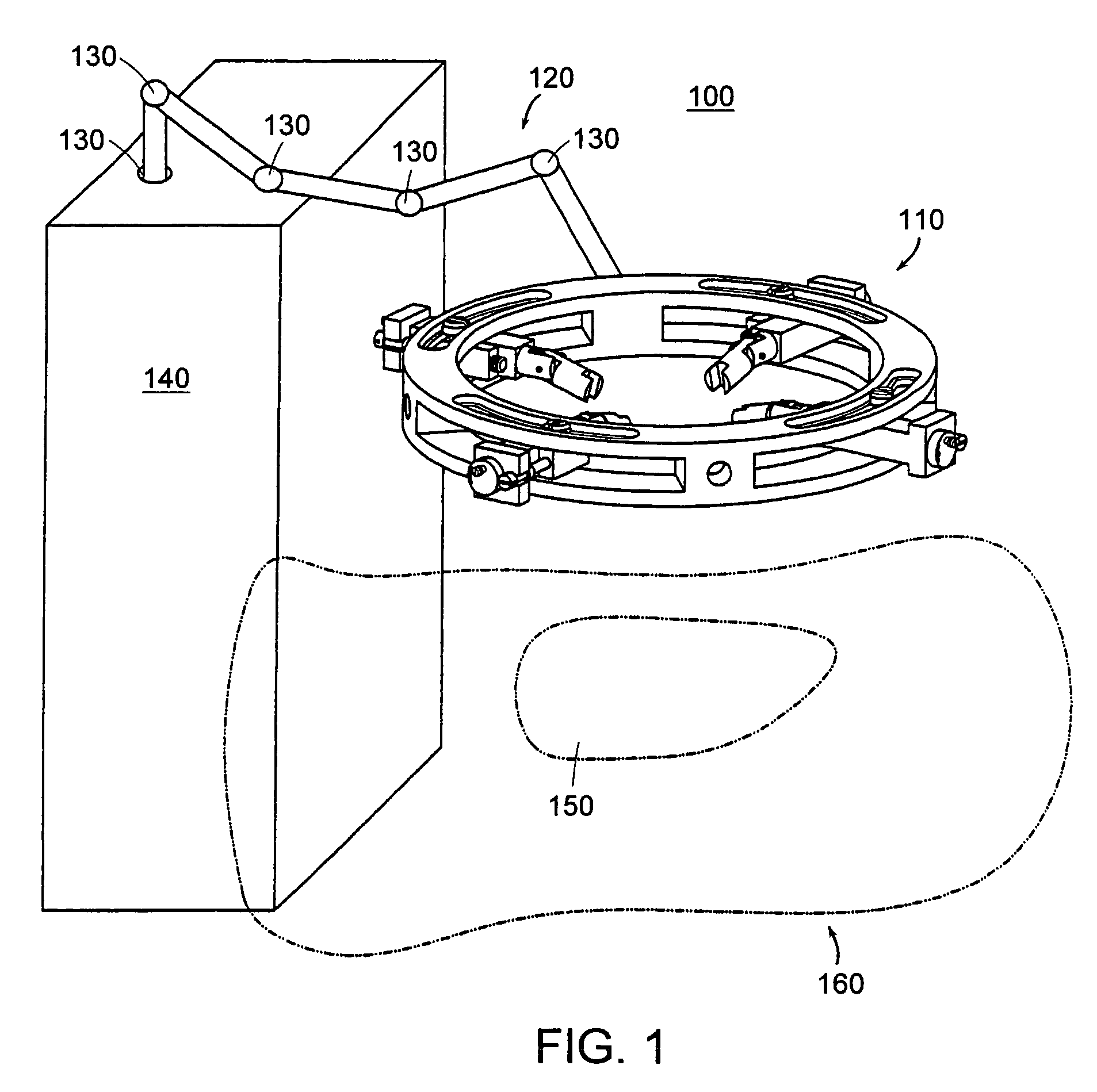
[0037]The present invention includes one embodiment of an adjustable retractor 100 of the invention for minimally invasive surgical access. The retractor 100 includes a frame 110 that is attachable to an arm 120 as shown in FIG. 1. Arm 120 is attached to a supporting structure 140, which can, for example, be a table, a rack, a cart, or the like. Arm 120 is preferably a surgical arm, such as a universal arm, which includes enough joints 130 to provide a desired number of degrees of freedom to easily adjust frame 110 over an incision 150 in a patient...


PUM


Abstract

A surgical retractor positioning device is provided to create a surgical working field in a minimally invasive and flexible manner. In one embodiment, the device can include a frame and an arm connected to the frame. The arm can include a proximal end, a distal end having a distal end axis, and a major axis, wherein the distal end axis is movable relative to the proximal end, whereby the distal end axis can intersect the major axis at an angle. The device can include at least one blade connected to the distal end of the arm, wherein the blade is fixably rotatable about the major axis. The device can include at least two arms.

Description

BACKGROUND OF THE INVENTION[0001]In surgical procedures, it is important to minimize trauma to the patient and damage to the tissue as much as possible. For that reason, surgeons try to keep incisions to a minimum while performing surgical procedures. However, the surgeon performing a delicate surgery must still be able to have a clear view of the operating field. Surgeons utilize retractors in an attempt to achieve the goal of keeping the incision to a minimum while still providing a clear view of the operating field.[0002]However, many current retractors have several shortcomings. For instance, it is often difficult to minimize the size of an incision and potential trauma while expanding or changing an operating field because current retractor systems typically provide a limited amount of maneuverability of the retractor blades. For example, some current retractor systems merely include retractor blades that are only able to translate along a limited number of axes. Expansion of t...

Claims


Application Information

Patent Timeline
Patent Type & Authority Patents(United States)
IPC IPC(8): A61B1/32A61B17/02A61B17/00A61B17/28A61B19/00
CPCA61B17/0293A61B17/0218A61B19/22A61B2017/00022A61B2017/2927A61B2017/2929A61B34/70
Inventor KIM, DANIEL H.
Owner DEPUY SPINE INC (US)
Why Eureka
Try Eureka