Optical fiber configuration for dissipating stray light

a technology of optical fiber and stray light, applied in the field of optical fiber, can solve the problems of preventing full utilization of the potential of cladding-pumped fiber devices, catastrophic heating, and the presence of “stray light” within the system, and achieve the effect of increasing the presence of stray ligh

Active Publication Date: 2008-10-14
FURAKAWA ELECTRIC NORTH AMERICA INC
View PDF26 Cites 43 Cited by
  • Summary
  • Abstract
  • Description
  • Claims
  • Application Information

AI Technical Summary

Benefits of technology

[0013]In accordance with the present invention, an optical transmission fiber is formed to include a relatively thin outer cladding layer disposed to surround the inner cladding layer and thus capture and contain stray light (including remaining pump light and / or refracted signal light). The limited thickness of the outer cladding permits stray light to propagating therealong while “leaking” or “tunneling” into the outer coating in a controlled manner. In a preferred embodiment, a thickness of no more than 10 μm (or, even better, 5 μm) is defined for the outer coating layer. By forcing the stray light to be dissipated along an extended portion of the outer coating, localized heating of the polymer outer coating will be virtually eliminated, preventing thermally-induced catastrophic failure of the fiber.
[0016]It is an aspect of the present invention that the inclusion of a thin (“leaky”) outer cladding layer may be utilized in virtually any fiber-based arrangement where thermal management of stray light is a concern. For example, fiber amplifiers, fiber-based lasers, laser combiner bundles, all generate a significant amount of stray light energy that can become problematic. Further, environmental situations (such as where a fiber needs to be confined in a bent position, or at a splice between different fiber sections) can increase the presence of stray light. In any of these situations, the inclusion of a thin outer cladding layer adjacent to a polymer-based fiber outer coating will controllably manage the dissipation of the stray light along an extended portion of the outer coating.

Problems solved by technology

A difficulty preventing full exploitation of the potential of cladding-pumped fiber devices is the problem of efficiently coupling a sufficient number of low brightness sources into the inner cladding.
Even though the DiGiovanni et al. tapered fiber bundle has been found to greatly improve the efficiency of coupling multiple optical signals into a fiber amplifier, laser or light combiner, problems attributed to the presence of “stray light” within the system remain to be solved.
While the prior art arrangement of FIG. 1 is capable of transmitting stray light with minimal attenuation and without heating the fiber, stray light may result in catastrophic heating if it is not permanently contained within the boundary of inner cladding 3.
In this situation, cladding light refracts into outer coating 4 where it is absorbed and generates an unwanted amount of localized heating.
If this heat is sufficiently localized, the fiber may be burned or otherwise damaged to the point of experiencing catastrophic failure.
Various other types of perturbations along the fiber may also result in increasing the presence of stray light along the fiber and thus potentially compound the problem of locally heating the fiber.
While these arrangements provide a certain degree of stray light management, the utilization of selected sections of fiber to provide this ability limits its usefulness.
For example, if a new splice is added to a fiber, or a bend is introduced in a new location, the absorbing fiber sections may not be properly located to dissipate additional stray light.

Method used


Image

  • Optical fiber configuration for dissipating stray light
  • Optical fiber configuration for dissipating stray light
  • Optical fiber configuration for dissipating stray light

Examples


Embodiment Construction

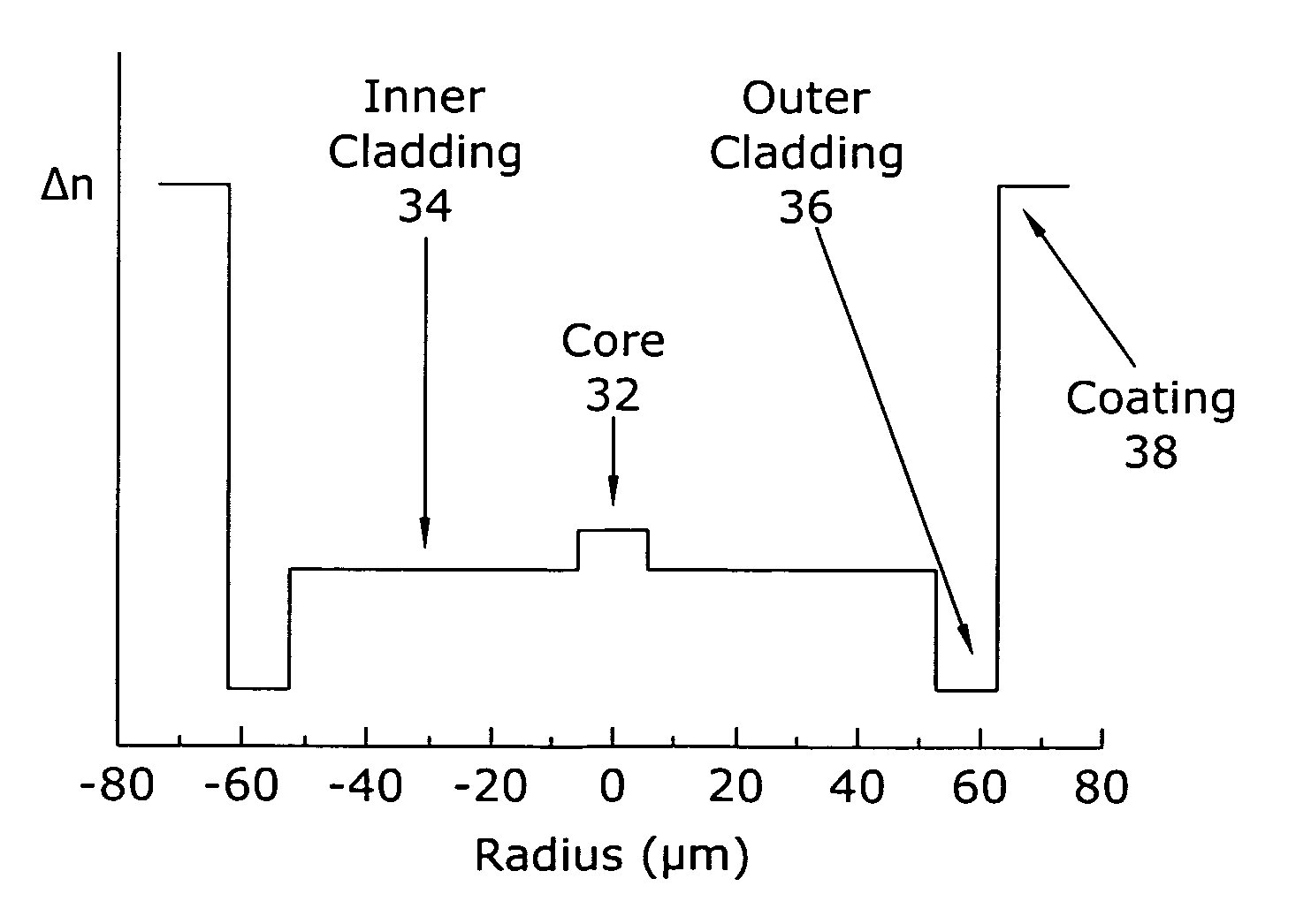
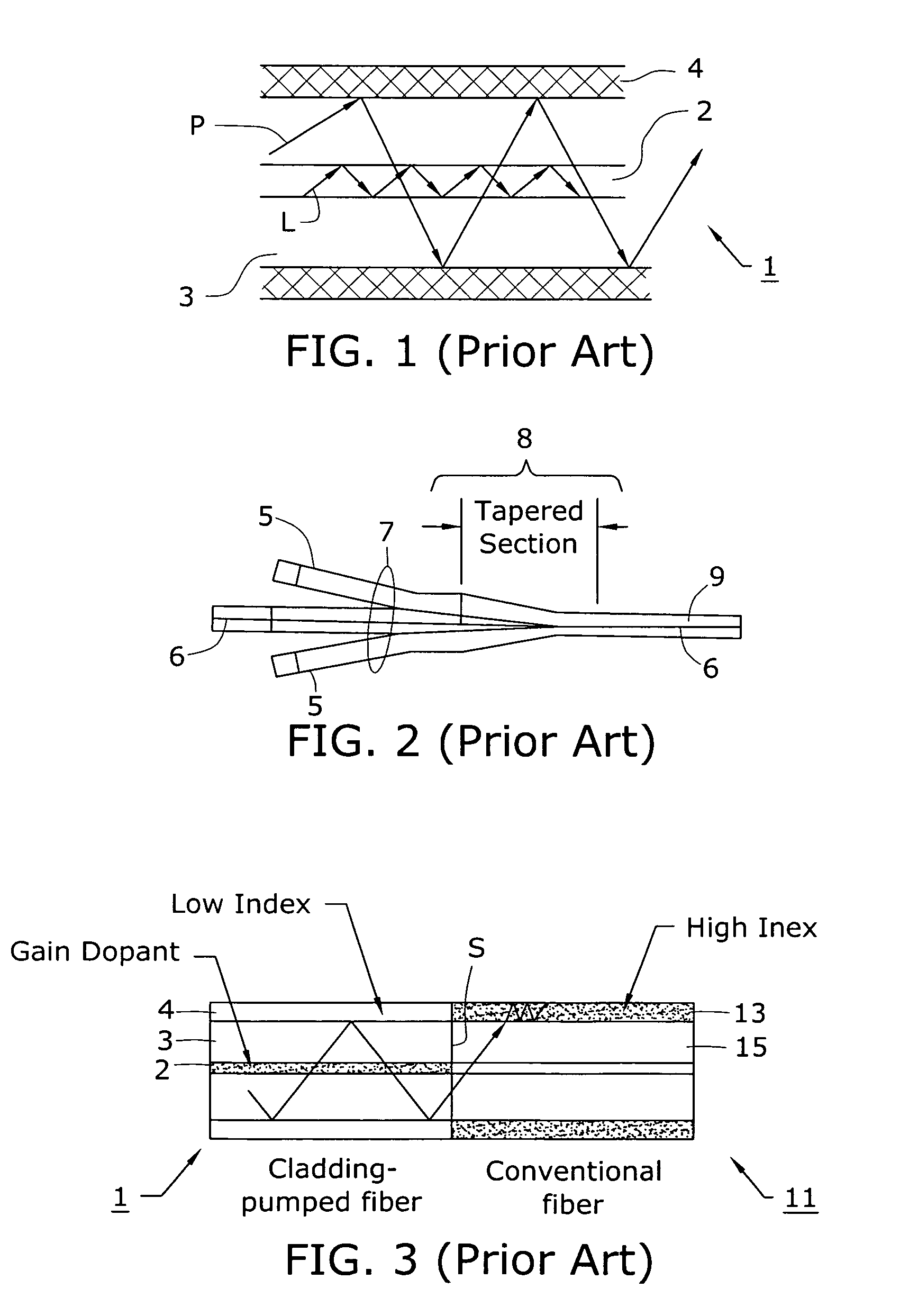
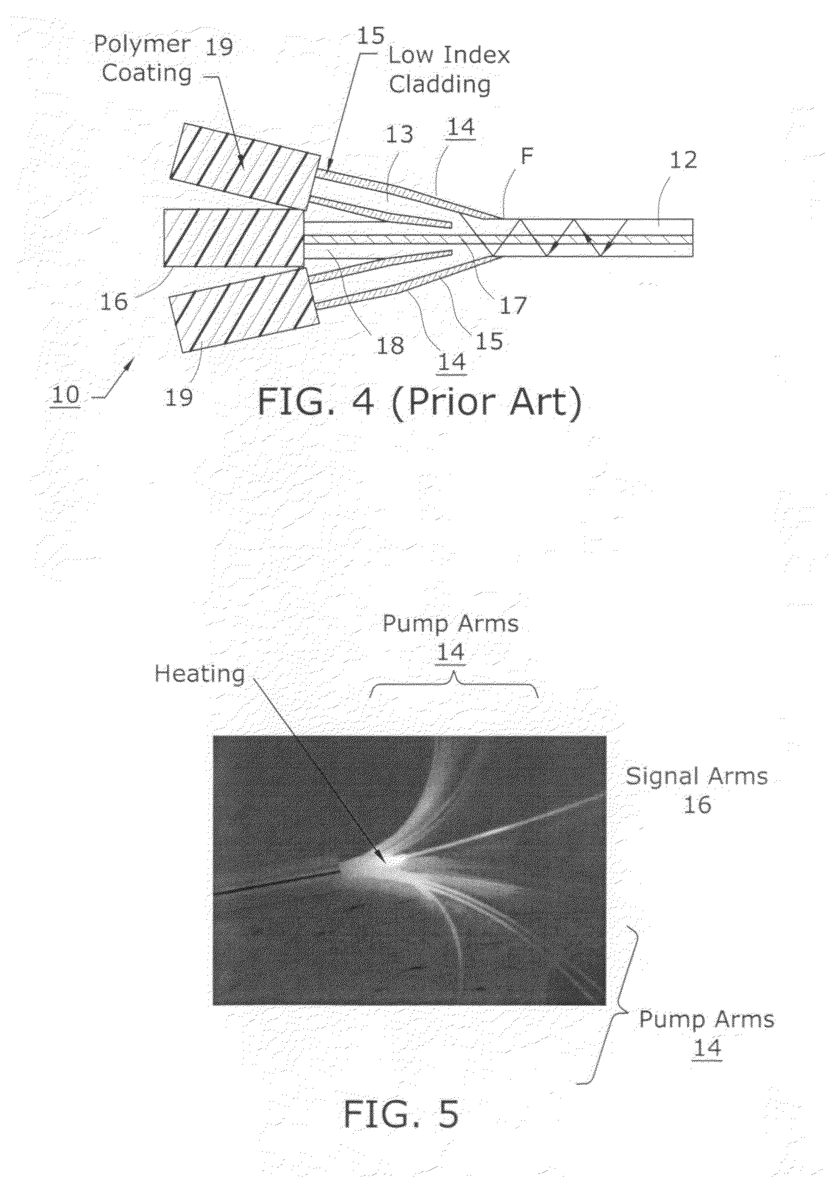
[0031]An exemplary prior art tapered fiber bundle 10 is shown in FIG. 4, in this case illustrating the propagation of backward-scattering stray light that re-enters bundle 10 from a cladding-pumped fiber 12 that is fused to bundle 10. Bundle 10 is illustrated as comprising a plurality of pump fibers 14 and a signal fiber 16. Using methods well-known in the art, bundle 10 is adiabatically tapered down until its outer diameter matches the outer diameter of cladding-pumped fiber 12 at location F, where the two fibers are then fusion spliced together. Signal fiber 16 comprises a core region 17 (which may be single mode or multimode), surrounded by a relatively large diameter (e.g., 125 μm) cladding layer 18. Pump fibers 14 comprise a relatively large silica core 13 (e.g., 105 μm) and a thin (e.g., 10 μm), low-index cladding layer 15. As discussed above, the refractive index of cladding layer 18 is less than the refractive index of core region 17 so as to confine the propagating signal l...


PUM


Abstract

An optical transmission fiber is formed to include a relatively low-index, relatively thin outer cladding layer disposed underneath the protective polymer outer coating. Stray light propagating along an inner cladding layer(s) within the fiber will be refracted into the thin outer cladding (by proper selection of refractive index values). The thin dimension of the outer cladding layer allows for the stray light to “leak” into the outer coating in a controlled, gradual manner so as to minimize heating of the coating associated with the presence of stray light. The inventive fiber may also be bent to assist in the movement of stray light into the coating.

Description

TECHNICAL FIELD[0001]The present invention relates to an optical fiber useful for managing the presence of stray light in fiber-based laser, amplifier or light combiner applications and, more particularly, to an optical fiber including a thin outer cladding layer disposed between an inner cladding and an outer coating, the thin outer cladding used to contain and manage any light (pump and / or signal) that is present in the inner cladding layer, and dissipate this stray light in a controlled manner to minimize heating of the fiber's outer coating.BACKGROUND OF THE INVENTION[0002]Cladding-pumped fiber devices, such as lasers, amplifiers and light combiners, are important in a wide variety of optical applications, including high power communication systems, light sources for printers, lasers for medical optics, and the like. A typical cladding-pumped optical fiber comprises a signal core and a plurality of cladding layers. The inner cladding surrounding the core is typically a silica cl...

Claims


Application Information

Patent Timeline
Patent Type & Authority Patents(United States)
IPC IPC(8): G02B6/02G02B6/26
CPCG02B6/0365G02B6/2804G02B6/02395G02B6/036G02B6/028
Inventor DIGIOVANNI, DAVID JOHNEMORI, YOSHIHIROFISHTEYN, MICHAELHEADLEY, CLIFFORD
Owner FURAKAWA ELECTRIC NORTH AMERICA INC
Why Eureka
Try Eureka