
Vascular Access Wound Sealing System and Method

Inactive Publication Date: 2011-10-06
BIOLIFE
View PDF3 Cites 140 Cited by
  • Summary
  • Abstract
  • Description
  • Claims
  • Application Information

AI Technical Summary

Benefits of technology

[0042]It is an object of the invention to eliminate the need for manual pressure, reduce TTA, reduce scarring and reduce complications. It is also an object of the invention to increase patient satisfaction. It is a further object that the closure means is an extra-luminal strategy with nothing left in the patient at discharge. It is a further object to lower cost.
[0043]It is a further object to secure bodily tissue with a Z-stitch encompassing the area defined by the catheter insertion site, and the vascular access site distal to the blood vessel. The ends of the sutures are tied together to form an X. Twisting the external ends to create torque and excessive tension on the stitch further enhances the X. The tissue perpendicular to the subcutaneous stitch indents downward towards the tract and arterial access site and provides low-level continuous pressure on the wound.
[0044]It is still a further object to seal the elongated suture holes to prevent oozing, bleeding and microbial colonization.

Problems solved by technology

During this time the patient typically experiences severe discomfort from the intense pressure.
BIOSEAL ADVANCED hemostatic agent significantly reduces the holding time for hemostasis but has no clinically proven effect on the TTA.
There are, however, several problems with internal closure devices:1. These devices are safe and effective when the doctor is skilled and careful.a. There is a published 10-30% complication rate with these devices.b. The devices are used only by the very skilled and shunned by the less skilled.2. The devices are expensive.a. They range in price from $200-$250 per device.3. Many dialysis patients visit the IR labs 2 to 4 times per year.
If the dialysis patient has to re-visit the IR lab in this time frame, the care the patient needs can be potentially compromised.4. Many practicing physicians are ethically resistant to devices left inside the body for extended periods of time.
'569 teaches this is particularly critical because excess tension can cause cosmetically unacceptable scaring.
Davis, U.S. Pat. No. 4,773,421, teaches a controlled linear tensioning device because excess tension of the suture can damage underlying skin.
Lafontaine et al, U.S. Pat. No. 5,964,782, teaches that the time to complete the suturing function can result in significant blood loss, particularly on arterial interventions.
Doctors work hard to prevent over-tightening sutures because it increases scarring and the potential for skin damage, so that excess tension and especially excess tension and torque is not used in clinical practice.
In addition, over-tightening elongates the hole and tends to prevent approximation at the distal end of the insertion site.
Heavy pressure has a large complication rate compared to semi-occlusive pressure including intense pain for the patient.
Other limitations of the related art will become apparent to those skilled in the art upon a reading of the specification and a study of the drawings.

Method used


Image

  • Vascular Access Wound Sealing System and Method
  • Vascular Access Wound Sealing System and Method
  • Vascular Access Wound Sealing System and Method

Examples


Embodiment Construction

[0071]A protocol has been developed for implementing the method of the present invention utilizing an anhydrous ferrate and cationic exchange resin composition (the powder) taught in U.S. Pat. No. 6,187,347, the entire teaching of which is incorporated herein by reference.

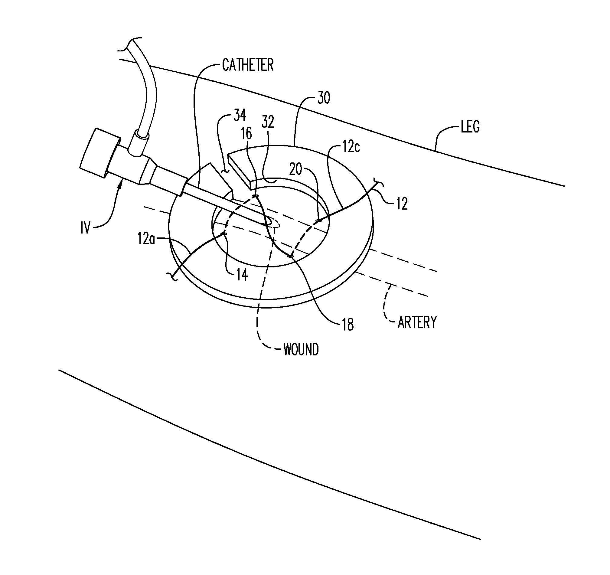
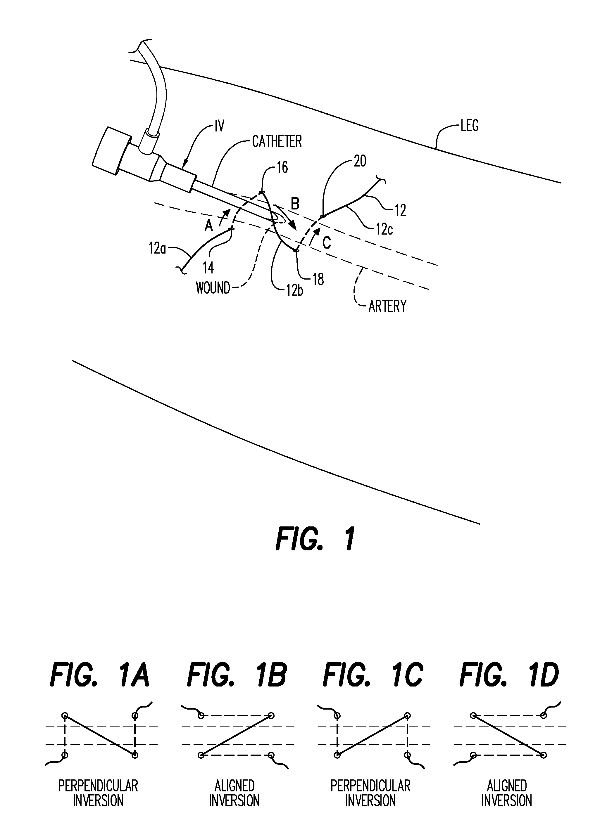
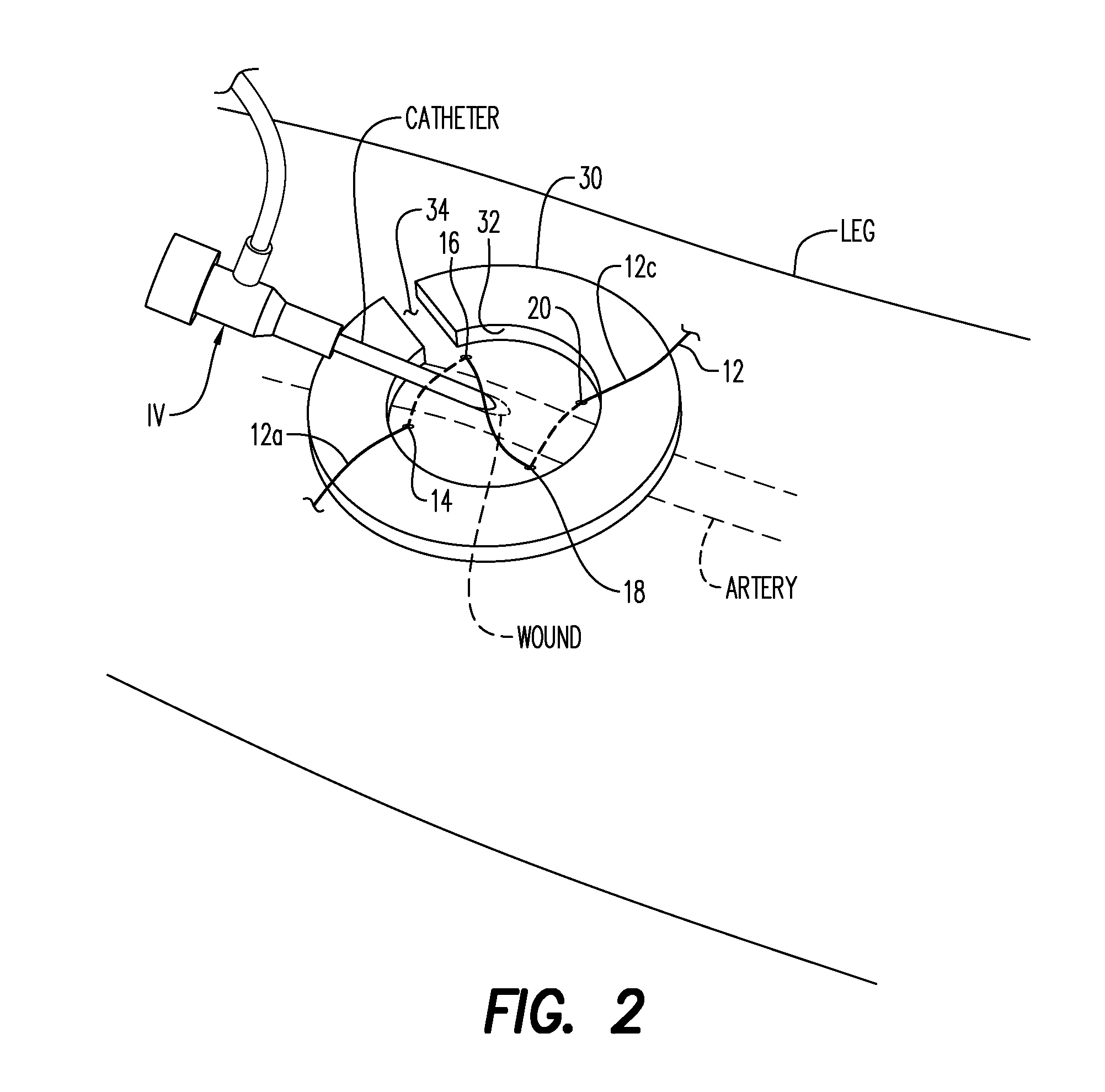
[0072]Referring now to the drawings, and firstly to FIG. 1 after an arteriogram or other vascular intervention within an artery of a leg is complete, while the catheter of the I.V. still remains in the artery and the wound tract, a suture 12 is placed into the skin at 14 adjacent the wound and under the skin and emerges at 16. The suture 12 is then diagonally over the catheter and into the skin a second time at 18 to reemerge at a fourth corner 20. Looking down and into the skin, the stitch pattern forms a “Z”, a typical stitch used to suture-close the stump after an appendectomy.

[0073]Referring now to FIGS. 1A, B, C, and D, there are four possible ways to configure the Z-stitch. FIGS. 1B and 1D create a skin inver...


PUM


Abstract

A wound sealing system and method for closing a vascular access site. The method invisions suturing a single continuous Z-stitch into a skin area around a wound and wound tract while the catheter remains within the vessel; covering the wound and suture holes with a hemostatic powder; tightening and knotting the ends of the suture together in an X configuration, applying finger pressure against the hemostatic powder as the catheter is removed; and twisting the suture ends together to tension the Z-stitch, pulling the skin area into inversion. The wound sealing system includes a powder containment device (PCD) which surrounds wound and catheter and a suture twisting member configured with the PCD to tension the Z-stitch closing the wound and arresting blood flow. The hole in the PCD holds a quantity of the hemostatic agent sufficient to cover the wound and suture holes.

Description

CROSS-REFERENCE TO RELATED APPLICATIONS[0001]Not applicableSTATEMENT REGARDING FEDERALLY SPONSORED RESEARCH OR DEVELOPMENT[0002]Not applicableINCORPORATION-BY-REFERENCE OF MATERIAL SUBMITTED ON A COMPACT DISC[0003]Not applicableBACKGROUND OF THE INVENTION[0004]1. Field of the Invention[0005]This invention relates generally to the field of vascular access procedures and more particularly to a suture tensioning concept for quickly arresting blood flow from a vascular access site.[0006]2. Description of Related Art[0007]Vascular access site closure has a long history of inventive strategies. The standard of care has always been simultaneous direct pressure on the vessel and the insertion site. This typically involves firm pressure over the access site at the skin surface and the vascular site at the surface of the artery or vein. Pressure is held for 10 to 30 minutes based on the blood chemistry and the blood's propensity to clot. During this time the patient typically experiences seve...

Claims


Application Information

Patent Timeline
IPC IPC(8): A61B17/04
CPCA61B17/0466A61L2400/04A61L26/0061A61B2017/0496
Inventor TEESLINK, REXBETTLE, GRISCOMKEENE, TALMADGE KELLY
Owner BIOLIFE
Learn More