Configurable measurement interface coupled to a front-end subsystem and a back-end subsystem for receiving a set of bootstrap information

a technology of a measurement interface and a back-end subsystem, which is applied in the direction of program control, instruments, error detection/correction, etc., can solve the problems of limiting the ability of designers to add more elaborate measurement functionality to a measurement device, imposing a significant increase in the complexity of the front-end subsystem of the measurement device, and limiting the ability to add more elaborate measurement functionality. , to achieve the effect of increasing the complexity

Active Publication Date: 2008-10-14
KEYSIGHT TECH
View PDF5 Cites 0 Cited by
  • Summary
  • Abstract
  • Description
  • Claims
  • Application Information

AI Technical Summary

Benefits of technology

[0005]A measurement device is disclosed having a configurable measurement interface that enables the dynamic allocation of responsibilities among front-end and back-end subsystems of a measurement device. A configurable measurement interface according to the present teachings enables the design of a measurement device that performs elaborate measurements without requiring an increase in the complexity of the front-end subsystem of the measurement device. A measurement device according to the present teachings includes a front-end subsystem for performing an interaction with a physical environment and back-end subsystem having a set of resources for supporting the front-end subsystem. The front-end and back-end subsystems are coupled to a measurement interface. The front-end subsystem transfers a set of bootstrap information via the measurement interface to the back-end subsystem and in response the back-end subsystem configures the resources to support the front-end subsystem.

Problems solved by technology

A relatively fixed allocation of responsibilities among the front-end and back-end subsystems of a measurement device may limit the ability of designers to add more elaborate measurement functionality to a measurement device without imposing a significant increase in the complexity of the front-end subsystem of the measurement device.
Unfortunately, an increase in the complexity of a front-end subsystem of a measurement device may increase development time and the overall cost a measurement device.

Method used


Image

  • Configurable measurement interface coupled to a front-end subsystem and a back-end subsystem for receiving a set of bootstrap information
  • Configurable measurement interface coupled to a front-end subsystem and a back-end subsystem for receiving a set of bootstrap information
  • Configurable measurement interface coupled to a front-end subsystem and a back-end subsystem for receiving a set of bootstrap information

Examples


Embodiment Construction

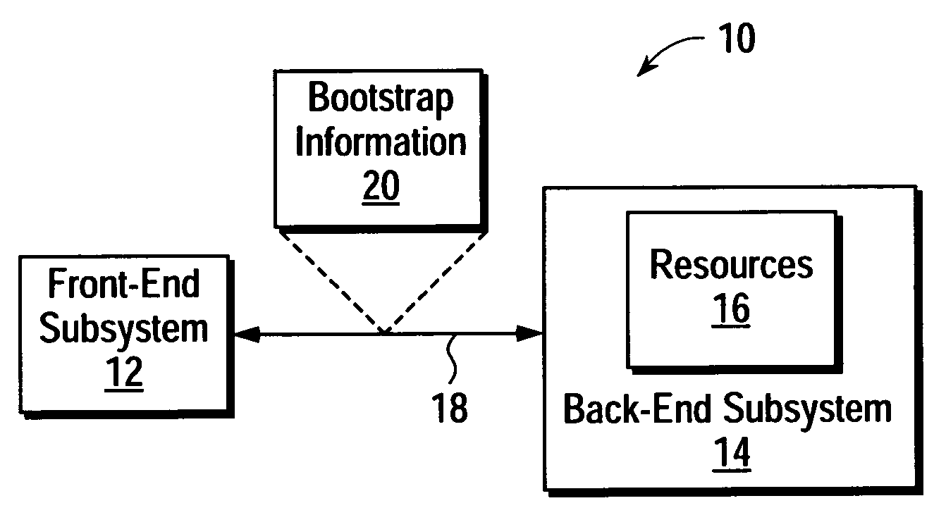
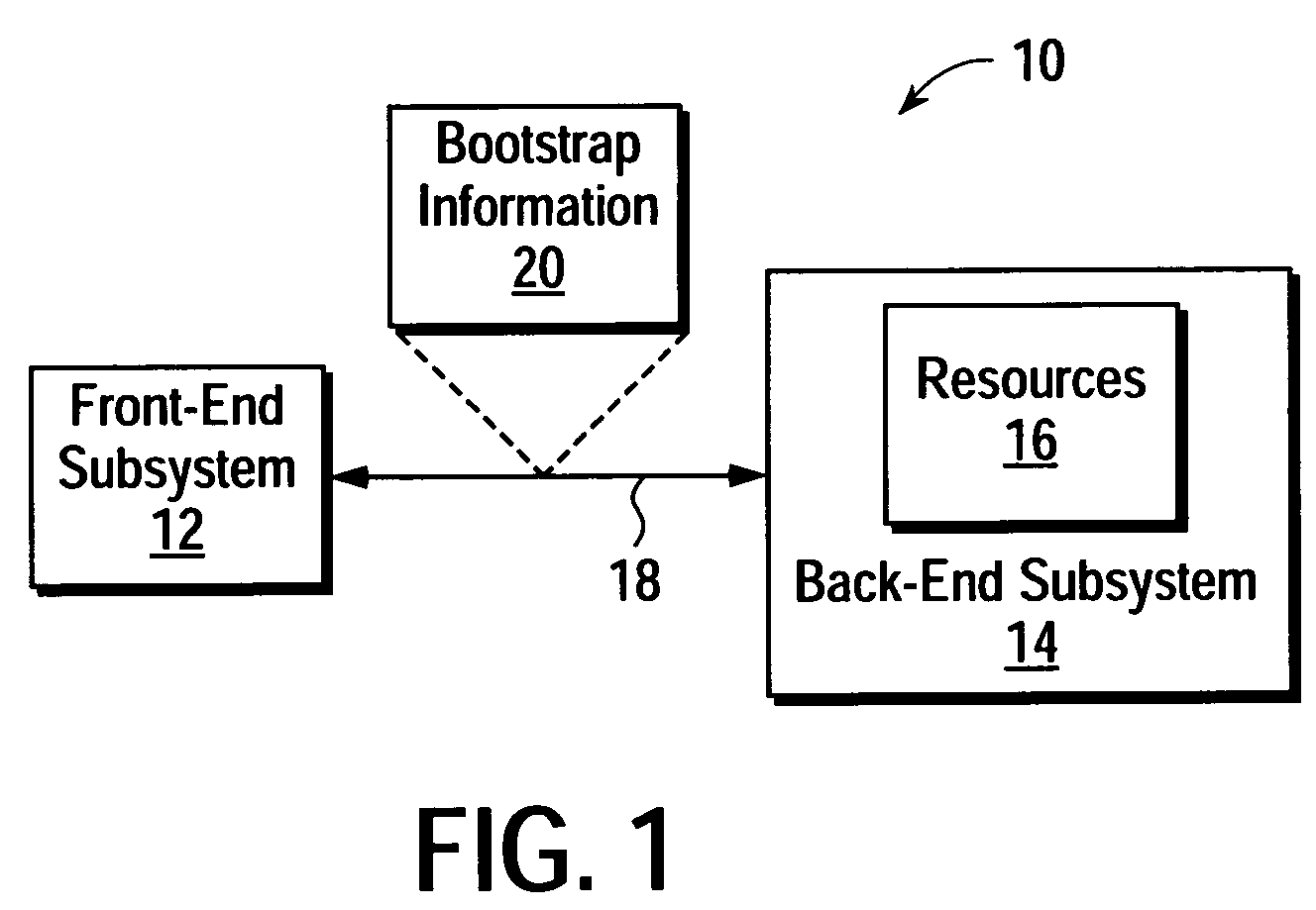
[0014]FIG. 1 shows a measurement device 10 that incorporates the present techniques. The measurement device 10 includes a front-end subsystem 12 and a back-end subsystem 14. The front-end and back-end subsystems 12-14 are interconnected via a measurement interface 18. The front-end subsystem 12 includes mechanisms for performing interactions with a physical environment and the back-end subsystem 14 includes a set of resources 16 for supporting the front-end subsystem 12. The front-end subsystem 12 dynamically configures the support functions of the resources 16 by transferring a set of bootstrap information 20 to the back-end subsystem 14 via the measurement interface 18.

[0015]The front-end subsystem 12 may use the bootstrap information 20 to adapt the functions performed by the resources 16 in the back-end subsystem 14 to the needs a particular application performed in the front-end subsystem 12. Examples of a functions that may be performed by the resources 16 and configured using...


PUM


Abstract

A measurement device having a configurable measurement interface that enables the dynamic allocation of responsibilities among front-end and back-end subsystems of a measurement device. A measurement device according to the present teachings includes a front-end subsystem for performing an interaction with a physical environment and back-end subsystem having a set of resources for supporting the front-end subsystem. The front-end and back-end subsystems are coupled to and communicate through a measurement interface. The front-end subsystem transfers a set of bootstrap information via the measurement interface to the back-end subsystem and in response the back-end subsystem configures the resources to support the front-end subsystem.

Description

BACKGROUND[0001]A wide variety of measurement devices may be arranged into separate subsystems that interact with one another via a measurement interface. For example, a wide variety of measurement devices, smart sensors, data acquisition systems, etc., may be arranged into a front-end subsystem and a back-end subsystem that communicate via a well-defined measurement interface. A measurement interface may be said to be well-defined if it provides a structure and protocol that enables a relatively independent design and deployment of the measurement device subsystems.[0002]One example of a well-defined measurement interface is one defined in the IEEE 1451.2 standard. The IEEE 1451.2 standard provides a measurement interface between a front-end subsystem (STIM) and a back-end subsystem (NCAP) of a measurement device. The IEEE 1451.2 standard sets forth a structure and protocol that enables an STIM to advertise to an NCAP an arrangement of measurement channels, measurement units, and s...

Claims


Application Information

Patent Timeline
Patent Type & Authority Patents(United States)
IPC IPC(8): G06F13/00G06F15/00G06F11/00G01D1/00G01D5/12G06F9/445G06F13/38G08C19/00
CPCG06F13/387G06F13/38G06F11/00G06F13/00
Inventor BURCH, JEFFERSON B.ENGEL, GLENN R.PURDY, JR., GLEN L.
Owner KEYSIGHT TECH
Why Eureka
Try Eureka