Apparatus and method for reducing execution latency of floating point operations having special case operands

a floating point operation and special case operand technology, applied in the field of processors, can solve the problems of degrading the overall processor performance, difficult parallelization, and increasing the implementation area

Active Publication Date: 2008-10-14
ORACLE INT CORP
View PDF68 Cites 18 Cited by
  • Summary
  • Abstract
  • Description
  • Claims
  • Application Information

AI Technical Summary

Benefits of technology

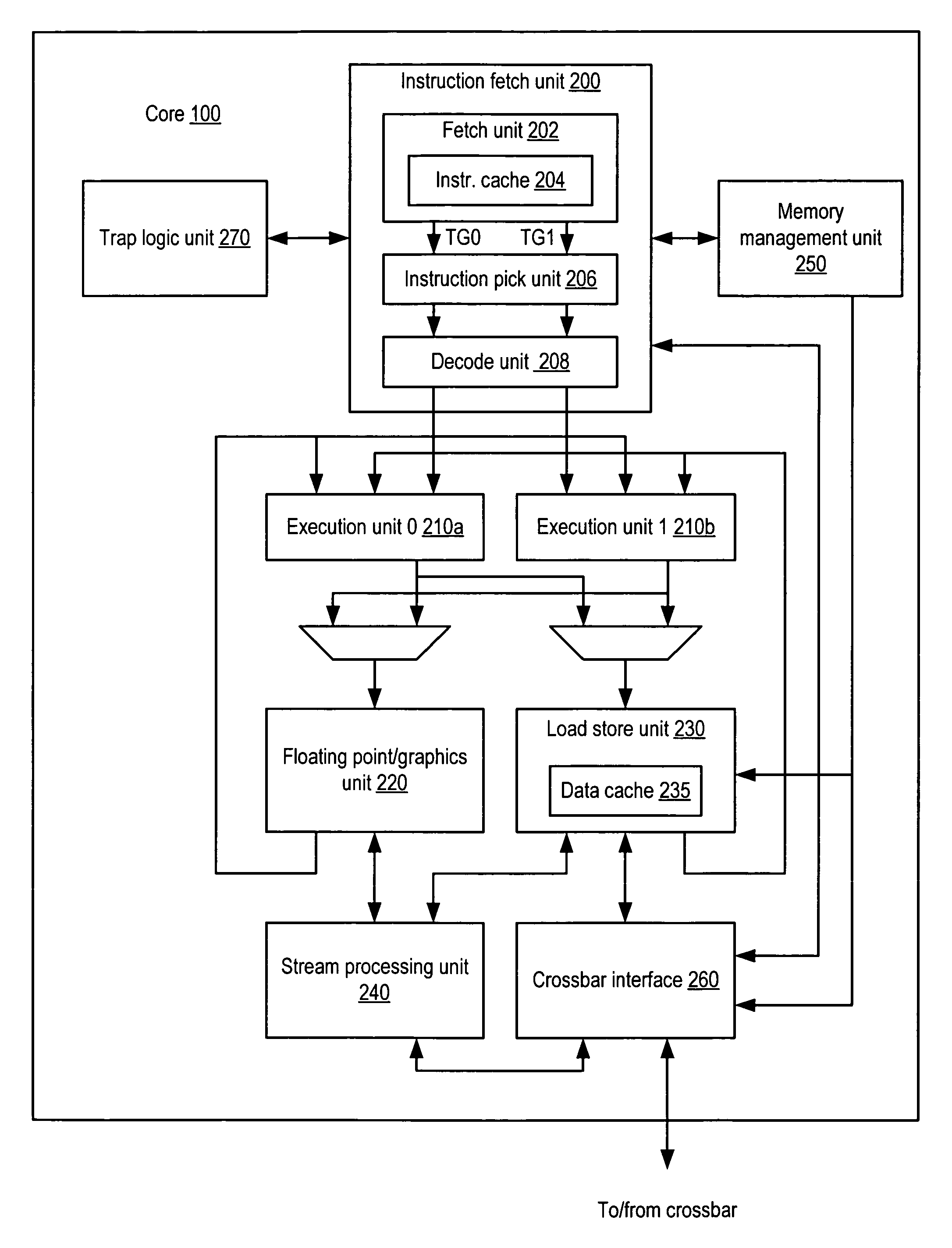
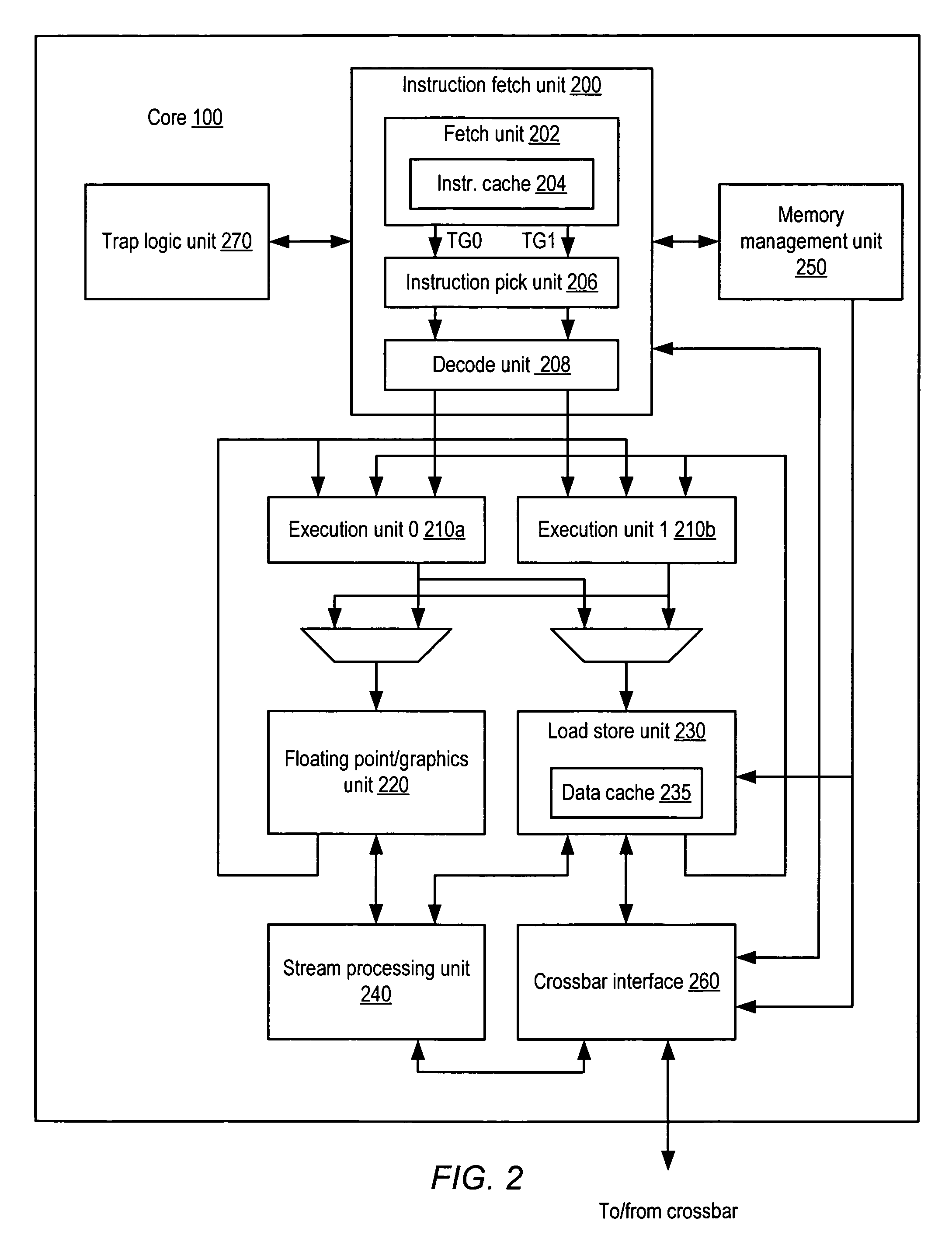
[0006]Various embodiments of an apparatus and method for floating-point special case handling are disclosed. In one embodiment, a processor may include a first execution unit configured to execute a longer-latency floating-point instruction, and a second execution unit configured to execute a shorter-latency floating-point instruction. In response to the longer-latency floating-point instruction being issued to the first execution unit, the second execution unit may be further configured to detect whether a result of the longer-latency floating-point instruction is determinable from one or more operands of the longer-latency floating-point instruction independently of the first execution unit executing the longer-latency floating-point instruction. In response to detecting that the result is determinable, the second execution unit may be further configured to flush the longer-latency floating-point instruction from the first execution unit and to determine the result.
[00...

Problems solved by technology

For example, common algorithms for evaluating divide and square-root instructions are iterative in nature and typically do not overlap well with other instructions such as addition and multiplication, particularly when the latter functions are pipelined.
However, completely segregating instruction implementation in this manner may result in increased implementation area due to the costs of providing independent resources to each execution unit, such as dedicated m...

Method used


Image

  • Apparatus and method for reducing execution latency of floating point operations having special case operands
  • Apparatus and method for reducing execution latency of floating point operations having special case operands
  • Apparatus and method for reducing execution latency of floating point operations having special case operands

Examples


Embodiment Construction

Overview of Multithreaded Processor Architecture

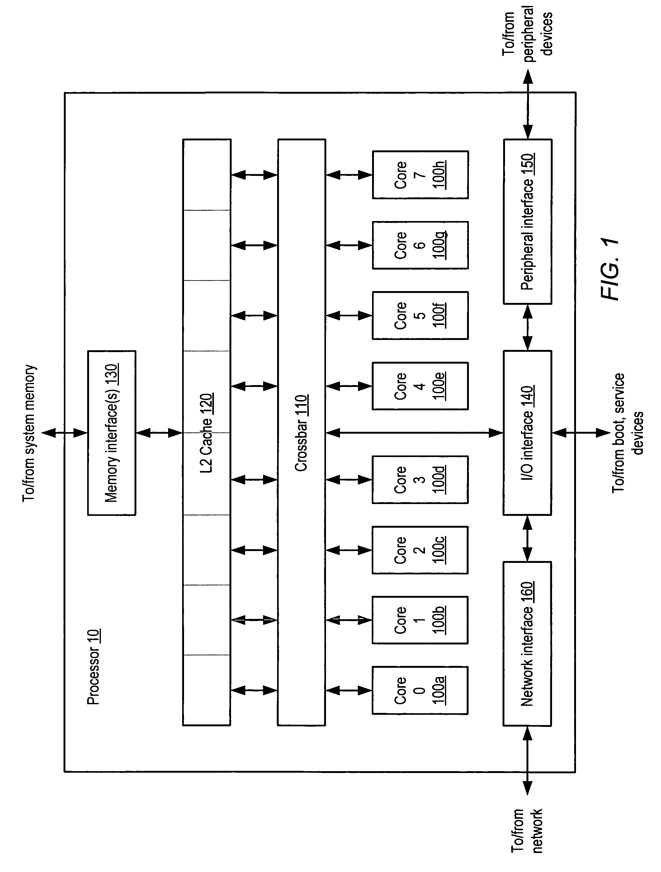
[0016]A block diagram illustrating one embodiment of a multithreaded processor 10 is shown in FIG. 1. In the illustrated embodiment, processor 10 includes a plurality of processor cores 100a-h, which are also designated “core 0” though “core 7”. Each of cores 100 is coupled to an L2 cache 120 via a crossbar 110. L2 cache 120 is coupled to one or more memory interface(s) 130, which are coupled in turn to one or more banks of system memory (not shown). Additionally, crossbar 110 couples cores 100 to input / output (I / O) interface 140, which is in turn coupled to a peripheral interface 150 and a network interface 160. As described in greater detail below, I / O interface 140, peripheral interface 150 and network interface 160 may respectively couple processor 10 to boot and / or service devices, peripheral devices, and a network.

[0017]Cores 100 may be configured to execute instructions and to process data according to a particular instruction s...


PUM


Abstract

An apparatus and method for floating-point special case handling. In one embodiment, a processor may include a first execution unit configured to execute a longer-latency floating-point instruction, and a second execution unit configured to execute a shorter-latency floating-point instruction. In response to the longer-latency floating-point instruction being issued to the first execution unit, the second execution unit may be further configured to detect whether a result of the longer-latency floating-point instruction is determinable from one or more operands of the longer-latency floating-point instruction independently of the first execution unit executing the longer-latency floating-point instruction. In response to detecting that the result is determinable, the second execution unit may be further configured to flush the longer-latency floating-point instruction from the first execution unit and to determine the result.

Description

BACKGROUND OF THE INVENTION[0001]1. Field of the Invention[0002]This invention relates to processors and, more particularly, to execution of floating-point arithmetic instructions.[0003]2. Description of the Related Art[0004]In many processor implementations that include support for floating-point arithmetic, different types of floating-point instructions are provided with distinct and dedicated resources for execution, often in distinct execution pipelines. For example, common algorithms for evaluating divide and square-root instructions are iterative in nature and typically do not overlap well with other instructions such as addition and multiplication, particularly when the latter functions are pipelined. Consequently, divide and square root instructions may be implemented in one execution unit according to one pipeline, while other instructions may be implemented in another execution unit according to a different pipeline. However, completely segregating instruction implementati...

Claims


Application Information

Patent Timeline
IPC IPC(8): G06F9/40
CPCG06F9/30123G06F9/3013G06F9/3828G06F9/3836G06F9/3857G06F9/3877G06F9/3885G06F9/3891G06F9/30014G06F9/3851G06F9/3858
Inventor BROOKS, JEFFREY S.OLSON, CHRISTOPHER H.
Owner ORACLE INT CORP
Why Eureka
Try Eureka