
Clamp tie

a technology of clamping and securing rods, which is applied in the direction of threaded fasteners, machine supports, other domestic objects, etc., can solve the problems of reducing the manufacturing time and material consumption, limiting the range of objects of prior devices, and maintaining uninterrupted transitions

Active Publication Date: 2008-10-21
HELLERMANNTYTON CORP
View PDF63 Cites 45 Cited by
  • Summary
  • Abstract
  • Description
  • Claims
  • Application Information

AI Technical Summary

Benefits of technology

[0008]Manufacturing time and materials are also reduced by preferably forming channels in the locking head to maintai

Problems solved by technology

Although effective in securing elongate items to each other, and adapted to slip over a supporting structure, neither of the devices shown in these patents made provision for supporting secured items about a standoff having a shouldered construction.
In addition to failing to compensate for shouldered support structures, prior devices had a fairly limited range of object diameters that could be secured thereby.
One reason that prior devices were limited to few diameters is because the prior devices maintained an uninterrupted transition from the locking head to the respective straps.
In other words, any object supporting structure extending from the locking heads of prior devices limited the range of strap motion, thereby limiting the sizes of elongate articles that could be bundled securely.
Although prior components solved problems associated with predecessor ties, the solutions involved designs incorporating substantial wall thickness, thereby requiring extensive cure time during manufacture and substantial raw materials.
Even where proper cure time was provided, the surfaces of the prior devices would exhibit deformations caused by the cooling of the material.

Method used


Image

  • Clamp tie
  • Clamp tie
  • Clamp tie

Examples


Embodiment Construction

[0016]Although the disclosure hereof is detailed and exact to enable those skilled in the art to practice the invention, the physical embodiments herein disclosed merely exemplify the invention which may be embodied in other specific structures. While the preferred embodiment has been described, the details may be changed without departing from the invention, which is defined by the claims.

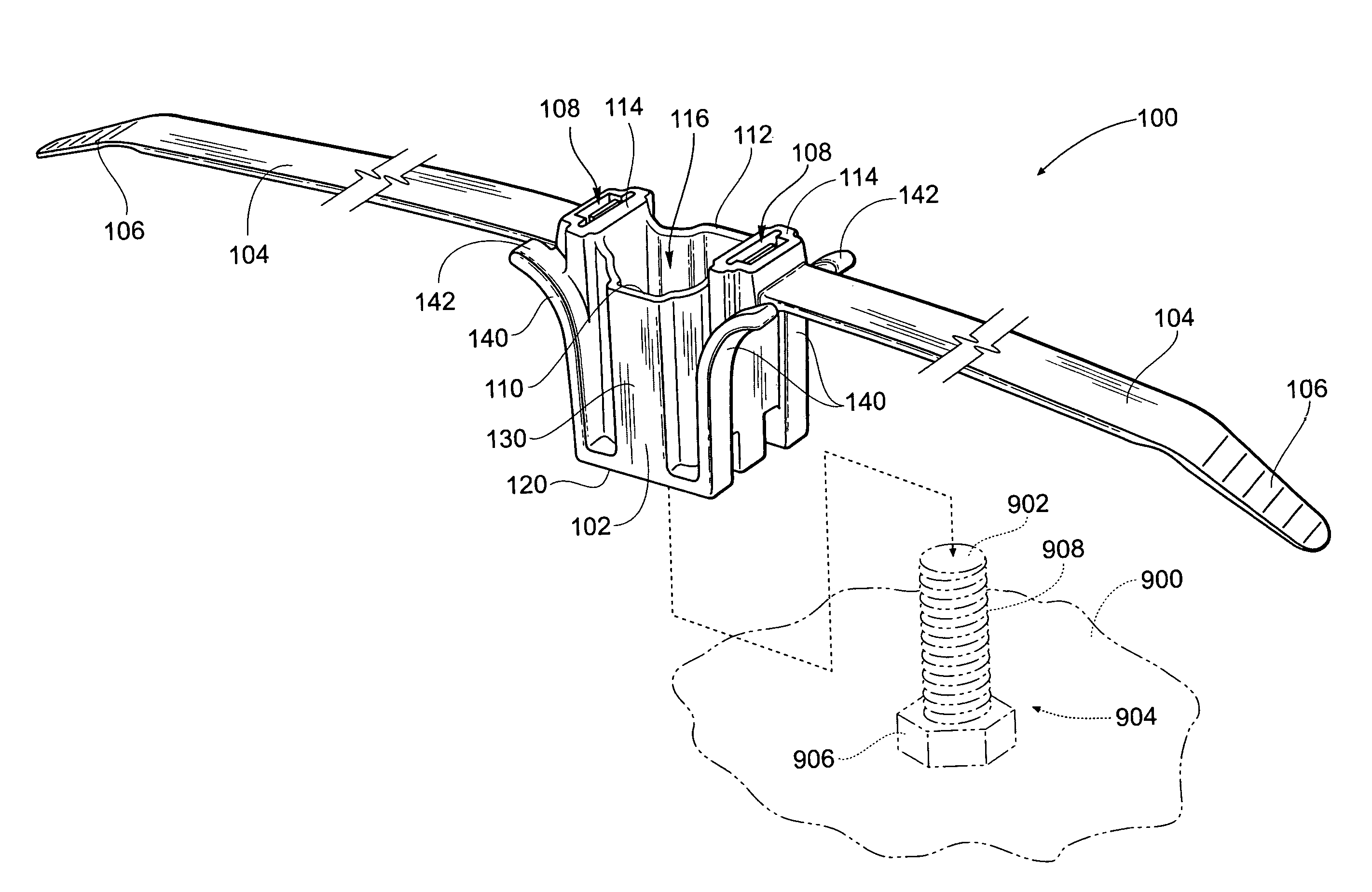
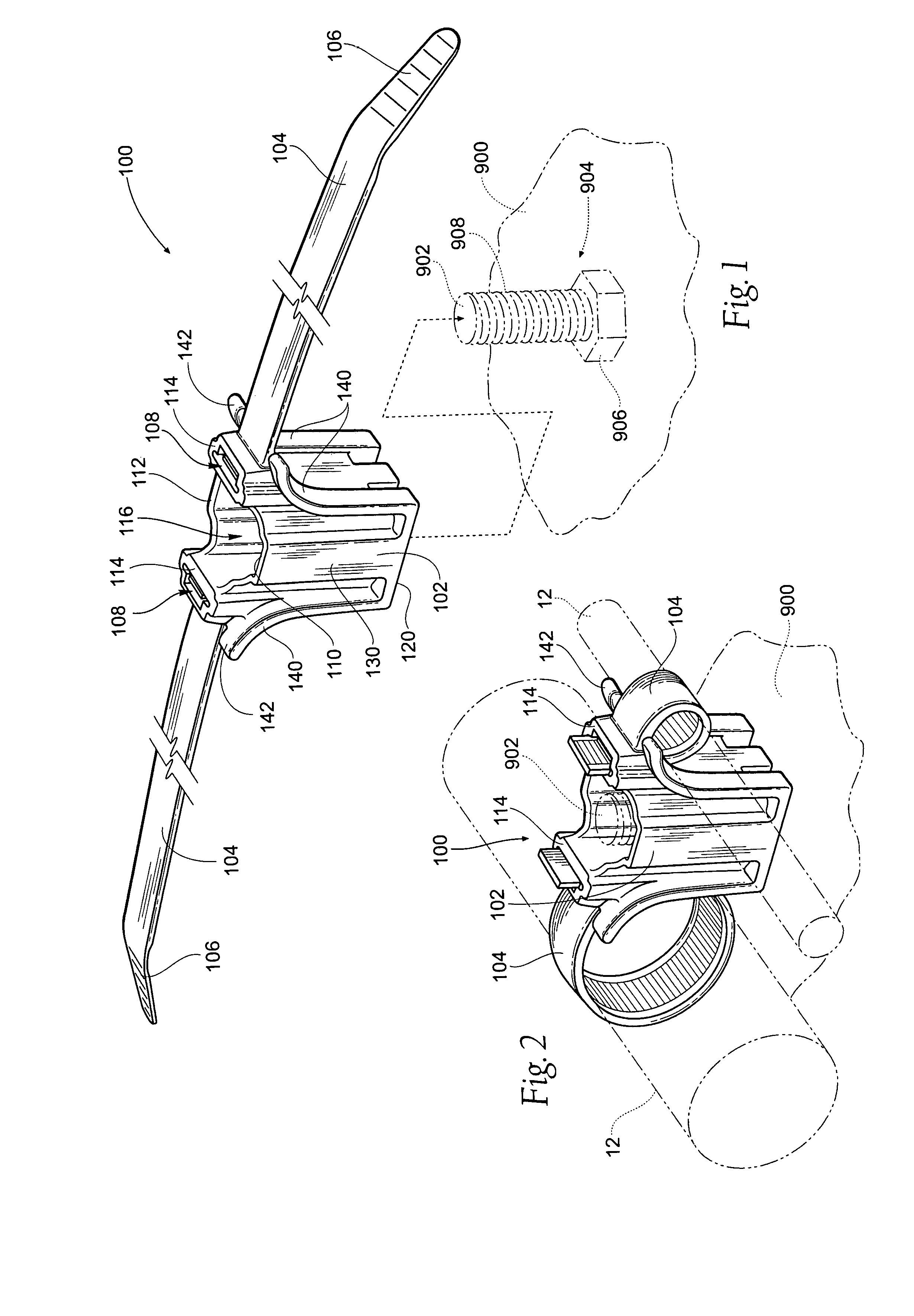
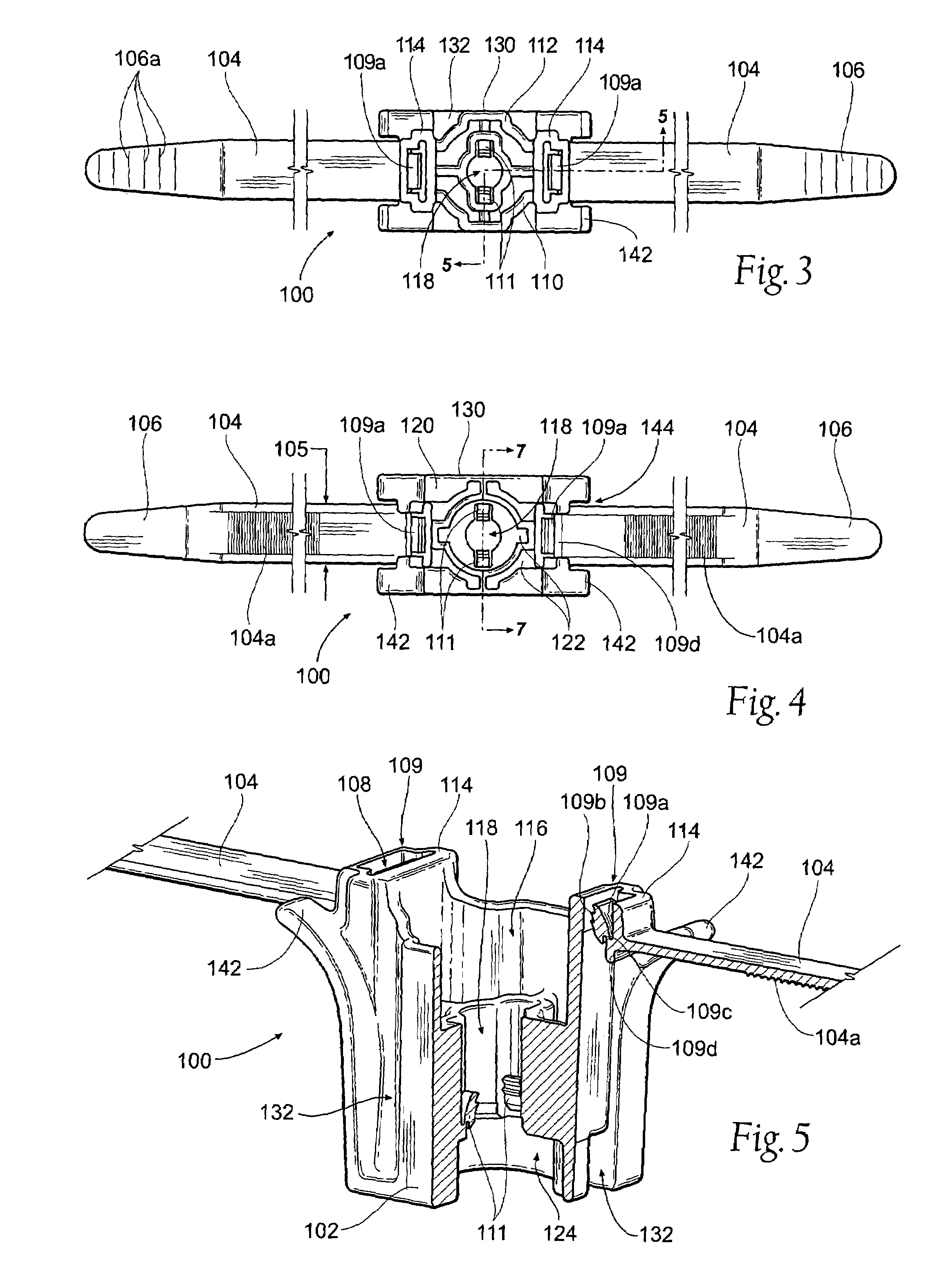
[0017]An embodiment of a clamp tie 100 embodying various features of the present invention is shown in FIG. 1 through FIG. 7. As best seen in FIG. 2, the tie 100 functions to hold elongate items 12 in a spaced relationship. The particular items 12 secured by the tie 100 are not critical and can comprise, wires, cables, tubes, conduits, fiber optics, vines or other such items as well as bundles made up of multiple ones of such items.

[0018]Prior to use, the tie 100 appears as shown in FIG. 1, including a locking head 102 and a pair of elongate straps 104 that extend from the locking head 102. The st...


PUM


Abstract

A clamp tie includes a locking head and flexible straps extending therefrom. The straps are insertable through the locking head to form spaced loops, which may secure items in a spaced relationship. Pawl mechanisms in the locking head secure the straps in looped configuration. An aperture through the locking head is provided for securing the tie to a mounting structure such as a shouldered mounting stud. An additional pawl mechanism may be provided within the aperture to secure the tie to the stud. Arcuate surfaces extend from the locking head, spaced from the straps, to further engage secured items. The upper and lower surfaces of the locking head have counterbores to receive mounting hardware and provide minimal variance of wall thickness throughout the locking head to reduce cure time and materials required for manufacture.

Description

BACKGROUND OF THE INVENTION[0001]This invention relates generally to devices for securing elongate items, such as wires, cables, hoses, tubing, conduits etc. More particularly, the invention relates to clamp ties that secure such items to a standoff in a spaced relationship to each other.[0002]Various devices have been developed for securing elongate items such as wires, cables, hoses, tubing, conduits, etc. Among these devices are clamps that secure a pair of such items in spaced, parallel relationship with each other. Examples of such clamps are shown in U.S. Pat. No. 5,966,781 and U.S. Pat. No. 6,240,602.[0003]Although effective in securing elongate items to each other, and adapted to slip over a supporting structure, neither of the devices shown in these patents made provision for supporting secured items about a standoff having a shouldered construction. Such need arises, for example, in the trucking, automotive or other industry wherein a pair of hoses, lines or cables are to ...

Claims


Application Information

Patent Timeline
IPC IPC(8): B65D63/00
CPCB65D63/1072F16L3/237Y10T24/1498F16B37/0857
Inventor GEIGER, GERARD G.PUNCOCHAR, MICHAEL E.
Owner HELLERMANNTYTON CORP
Learn More