Emission control system

a technology of emission control and waste gas, which is applied in the direction of lighting and heating apparatus, combustion process, combustion treatment, etc., can solve the problems of large media consumption disadvantage, relative high operating cost, and high installation cost, and achieves effective and low-cost disposal, increase in plasma volume, and increase the volume of waste gas

Inactive Publication Date: 2008-10-21
CENTROTHERM CLEAN SOLUTIONS GMBH & CO KG
View PDF9 Cites 16 Cited by
  • Summary
  • Abstract
  • Description
  • Claims
  • Application Information

AI Technical Summary

Benefits of technology

[0012]Therefore, the object of the invention is to provide a waste gas cleaning system in which use of a plasma source working even at atmospheric pressure permits effective and low-cost disposal of environmentally harmful or toxic gases or vapors.
[0013]The problem on which the invention is based is solved by a waste gas cleaning system of the type mentioned at the beginning in that the outlet of the reaction chamber is connected with a liquid jet, in that the liquid jet pump generates a negative pressure in the reaction chamber and in the plasma source, and in that the waste gases treated in the plasma or by excited particles are carried out of the reaction chamber together with the liquid carried through the pump, intermixed with the latter.
[0014]A negative pressure in the range of atmospheric pressure down to <100 mbar can be generated in the reaction chamber by use according to the invention of a liquid jet pump. At the same time, the harmful solid, gaseous and liquid substances still found in the waste gas stream after passage through the plasma are scrubbed out by the liquid jet.
[0015]Owing to the possibility of being able to vary the pressure in the reaction chamber over a broad range, the plasma may be ignited at low pressure, and the plasma conditions may be adapted so that decomposition of the gases or vapors to harmless waste gases is effected as fully as possible. In general, a reduction in pressure leads to an increase in plasma volume, but, on the other hand, the volume of waste gas is increased so that residence time is reduced.
[0016]Care should be taken to see that a plasma source is used that, owing to its structural features, is able to form as homogeneous as possible a large-volume plasma in the required pressure range and one that can be used in continuous operation. The waste gas to be treated can be conducted directly through the plasma of the plasma source or fed immediately behind the plasma source into the reaction chamber and treated by the particles excited in the plasma in the so-called remote plasma.
[0017]In development of the invention, the suction port of the liquid jet has a large cross section in order, on the one hand, to generate the required pumping capacity and, on the other, to prevent obstructions by solid constituents of the waste gas. This also results in especially thorough mixing of the liquid conducted through the liquid pump with the waste gas flowing out of the reaction chamber.

Problems solved by technology

In such waste gas cleaning systems, the relatively high operating costs and great consumption of media are disadvantageous.
Also disadvantageous is that many different media (burnable gases, oxygen) are required and that fairly high installation costs are to be expected.
There the disadvantage is that intervention in the vacuum system of the coating or etching system cannot be avoided, so that waste gas disposal may negatively influence the preceding semiconductor process.
In this connection, the fact that the plasmas generated often become constricted is to be regarded as disadvantageous.
In addition, the plasma volume obtainable is limited by screening effects.
As a result, the quantity of disposable waste gas is also limited, so that the quantities of waste gas obtainable in conventional combination systems (burning / thermal decomposition and subsequent scrubbing) cannot be obtained.
However, even in the most careful design of the plasma source, it is necessary to reduce the pressure in the reaction chamber for ignition of the plasma to some 10 mbar.
In addition, the fact that when working under normal pressure the most favorable plasma parameters for conversion of the gases or vapors are not always adjustable proves to be disadvantageous.

Method used


Image

  • Emission control system
  • Emission control system

Examples


Embodiment Construction

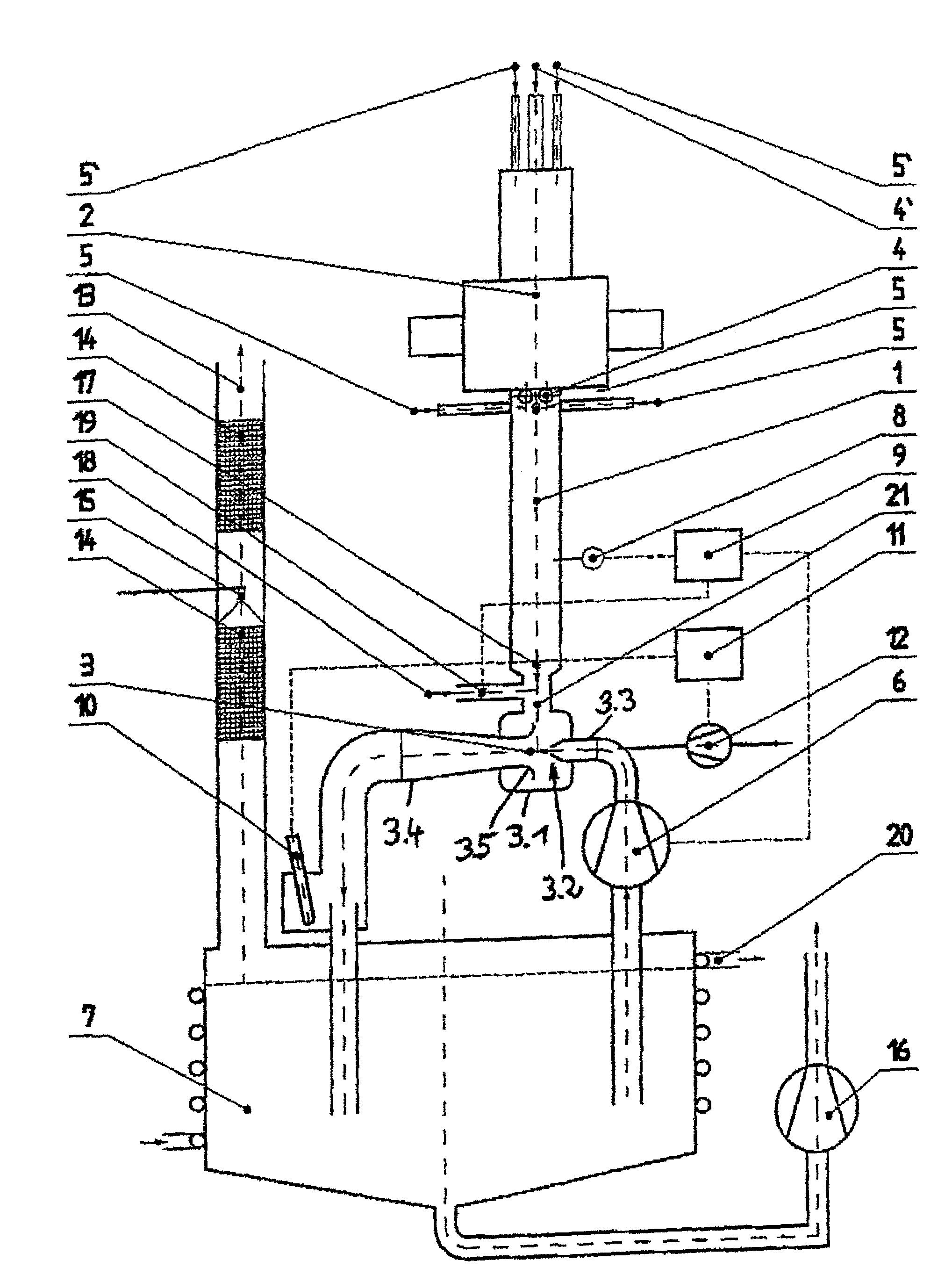
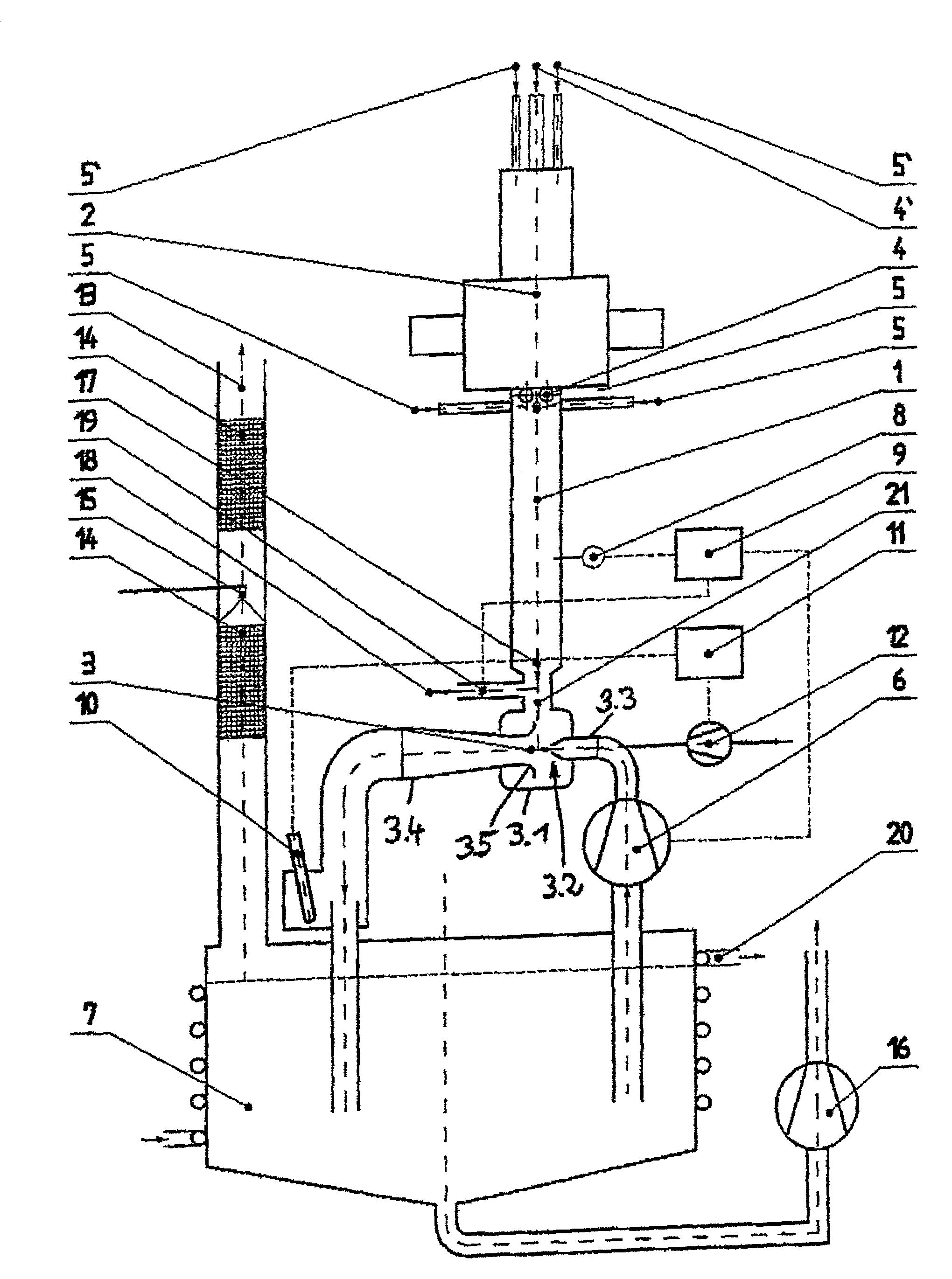
[0032]The waste gas cleaning system consists of a reaction chamber 1, arranged vertically, and is connected at its upper end with a plasma source 2. Plasma source 2 is arranged so that excited particles in the plasma source can be fed into the reaction chamber. A microwave source that works at a frequency of 2.45 GHz and is designed for a power of up to 6 kW is a possible plasma source 2.

[0033]The reaction chamber 1 in addition has at its upper end one or more inlets 4 for process gases or vapors to be disposed of, for example. process waste gases from semiconductor manufacturing processes, as well as one or more side inlets 5 for additional gas. Oxygen, hydrogen and water vapor, or a combination thereof, are possible additional gases. When the process gases or vapors and the additional gas are to be fed directly into the plasma source 2, the plasma source 2 should likewise be provided with one or more inlets 4′ for the process gases or vapors and one or more inlets 5′ for additiona...


PUM

PropertyMeasurementUnit
excitation frequencyaaaaaaaaaa
microwave poweraaaaaaaaaa
pressureaaaaaaaaaa

Abstract

The invention relates to an emission control system for removing environmentally harmful and/or toxic gases or vapors, comprising a reaction chamber which is connected to a plasma source, whereby plasma is formed in said reaction chamber by injecting excitation energy, and the reaction chamber and/or the plasma source has at least one inlet for the introduction of gases or vapors and one outlet for the gases or vapors which are treated in the plasma source and/or reaction chamber. According to the invention, the outlet of the reaction chamber is connected to a liquid jet pump which produces a low pressure in the reaction chamber and in the plasma source. The waste gases with the plasma or the waste gases which are treated by excited particles are jointly conducted along with the liquid which is circulated through the liquid jet pump, mixed therewith and discharged from said reaction chamber.

Description

BACKGROUND OF INVENTION[0001]The invention relates to a waste gas cleaning system for the disposal of environmentally harmful and / or toxic gases or vapors having a reaction chamber that is connected with a plasma source in which a plasma is formed by coupled excitation energy, where the reaction chamber and / or the plasma source has at least one inlet for the feed of gases or vapors and the reaction chamber has an outlet for the gases or vapors treated in the plasma source and / or in the reaction chamber.[0002]A variety of methods have been disclosed for cleaning environmentally harmful and / or toxic gases or vapors, such as for example waste gases coming from semiconductor manufacturing processes such as CVD, LP-CVD, plasma-CVD, plasma etching or similar processes. In the great majority of cases, methods in which the gases or vapors are burned and / or thermally decomposed are used. The thermally treated gases or vapors are then passed through a scrubber in which the solid and / or solubl...

Claims


Application Information

Patent Timeline
Patent Type & Authority Patents(United States)
IPC IPC(8): B01J19/08B01D53/32B01D53/75B01D53/77B01D53/79F23G7/06F23J15/02H05H1/24
CPCB01D53/32B01D53/75B01D53/77B01D53/79F23G7/061F23J15/02H05H1/24B01J2219/0894F23G2204/201F23J2219/40H05H1/46H05H1/461
Inventor FABIAN, LUTZKRODEL, GUNTERRESCH, DIETMARSTELZER, HORT
Owner CENTROTHERM CLEAN SOLUTIONS GMBH & CO KG
Why Eureka
Try Eureka