Vibration wave driving apparatus

a driving apparatus and vibration wave technology, applied in the direction of electrical apparatus, piezoelectric/electrostrictive/magnetostrictive devices, piezoelectric/electrostriction/magnetostriction machines, etc., can solve the problems of limited output torque squeak, and abrasion of vibration wave motors, so as to reduce the localized abrasion of contact members and reduce the inclination of contact surfaces

Inactive Publication Date: 2008-10-21
CANON KK
View PDF6 Cites 3 Cited by
  • Summary
  • Abstract
  • Description
  • Claims
  • Application Information

AI Technical Summary

Benefits of technology

[0018]The present invention provides a construction which reduces a change in the inclination of the contact surface of a contact member when the contact member contacts with a moving element or a vibration element, thereby reducing the localized abrasion of the contact member.

Problems solved by technology

If the frictionally sliding portion is simply widened to mitigate this, portions which do not coincide with vibration displacement increase therein, thus resulting in the cause of abrasion, squeak or the like.
The concentration of such a contact reaction force may become the cause of the localized abrasion or abnormal vibration of a material producing friction in the vibration member and the contact portion, and may spoil the performance of the vibration wave motor.
Output torque may be considered to be substantially proportional to the pressure force and thus, the output torque of the vibration wave motor is limited.
However, this vibration wave motor is similar to the vibration wave motor according to an example of the prior art shown in FIG. 14 in that the contact portion 205 is of cantilever structure, and there is the undesirable possibility that localized abrasion may be caused by such a contact state between the vibration element and the contact portion as shown in FIG. 17 to thereby deteriorate the performance of the vibration wave motor.
Further, in the contact portion, it is necessary to follow up to a sufficiently high frequency relative to the driving frequency of the vibration element to thereby keep stable contact, but when the contact portion is divided as shown in FIGS. 15A and 15B, the rigidity of each contact portion is reduced and the follow-up property becomes bad.
Therefore, to keep the follow-up properties of the contact portions equal to each other, it becomes necessary to make the contact portions into a more minute shape, but this requires much time and labor for manufacture, and results in a higher cost.
As described above, in the construction of the conventional vibration wave motor, there is the problem that durability is reduced by the localized abrasion between the vibration element and the contact portion.

Method used


Image

  • Vibration wave driving apparatus
  • Vibration wave driving apparatus
  • Vibration wave driving apparatus

Examples


first embodiment

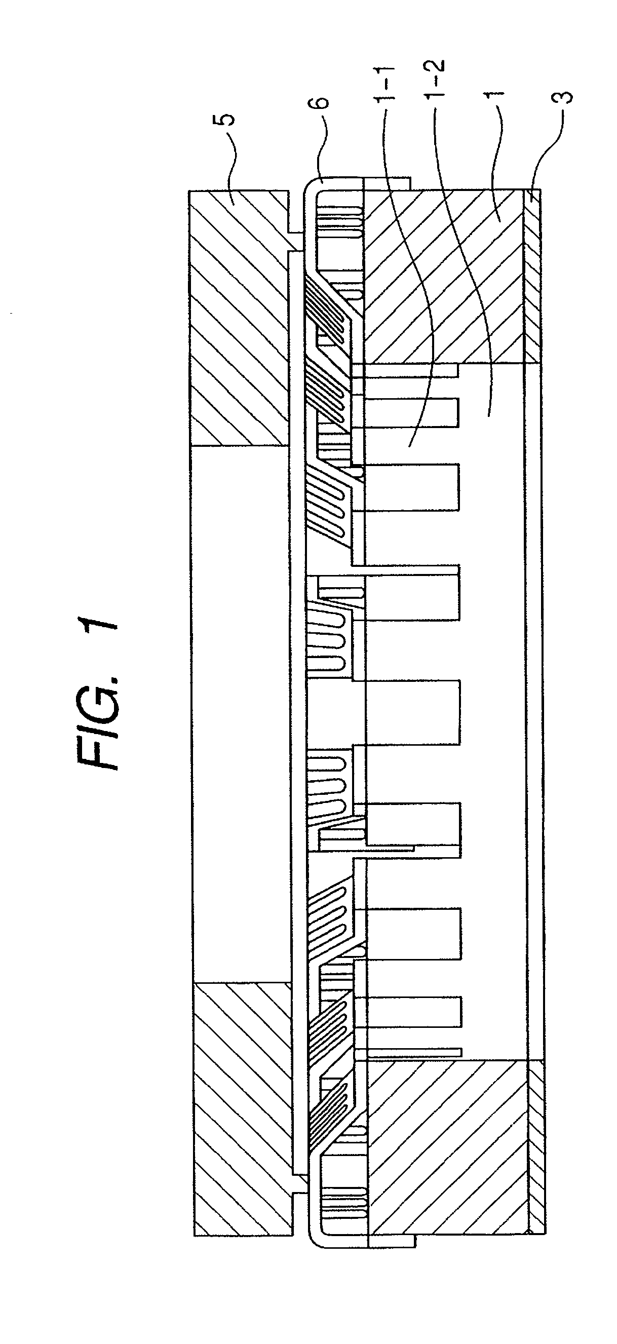
[0046]FIG. 1 is a cross-sectional view showing the construction of a vibration wave motor as a vibration wave driving apparatus according to a first embodiment of the present invention.

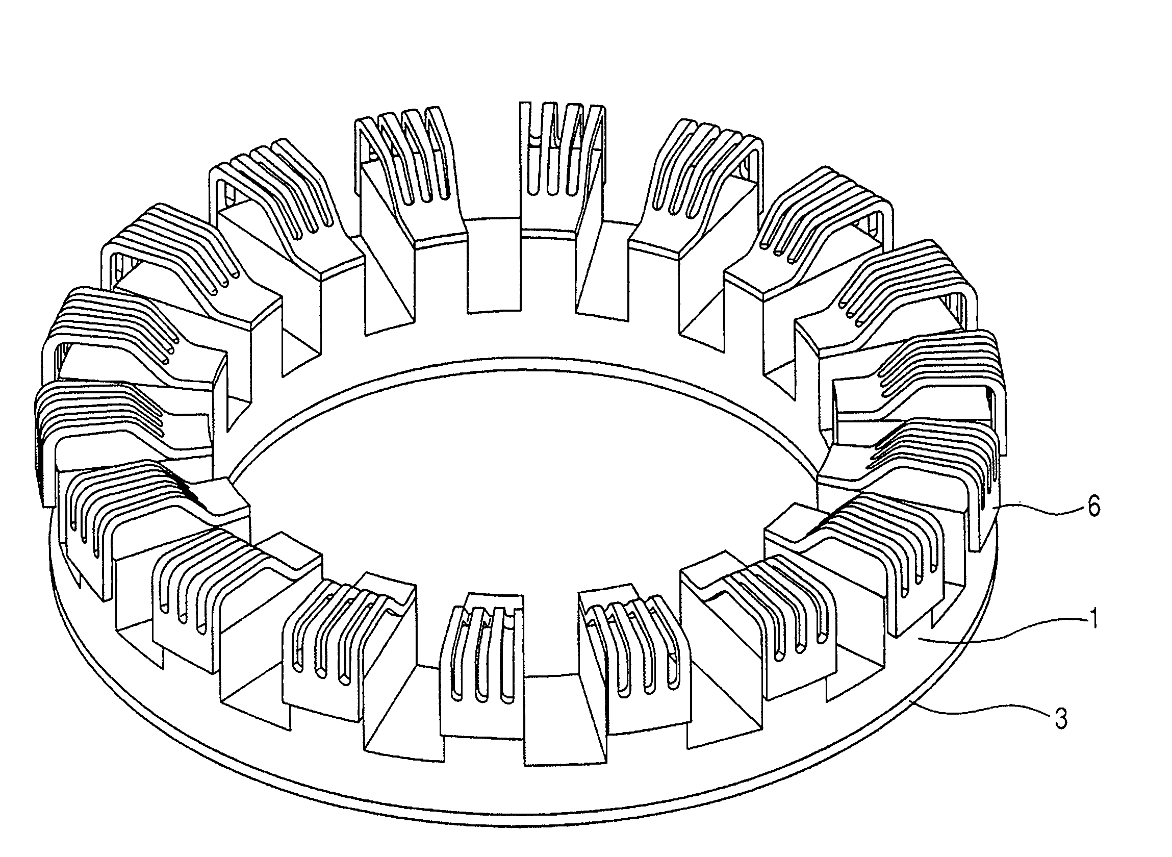
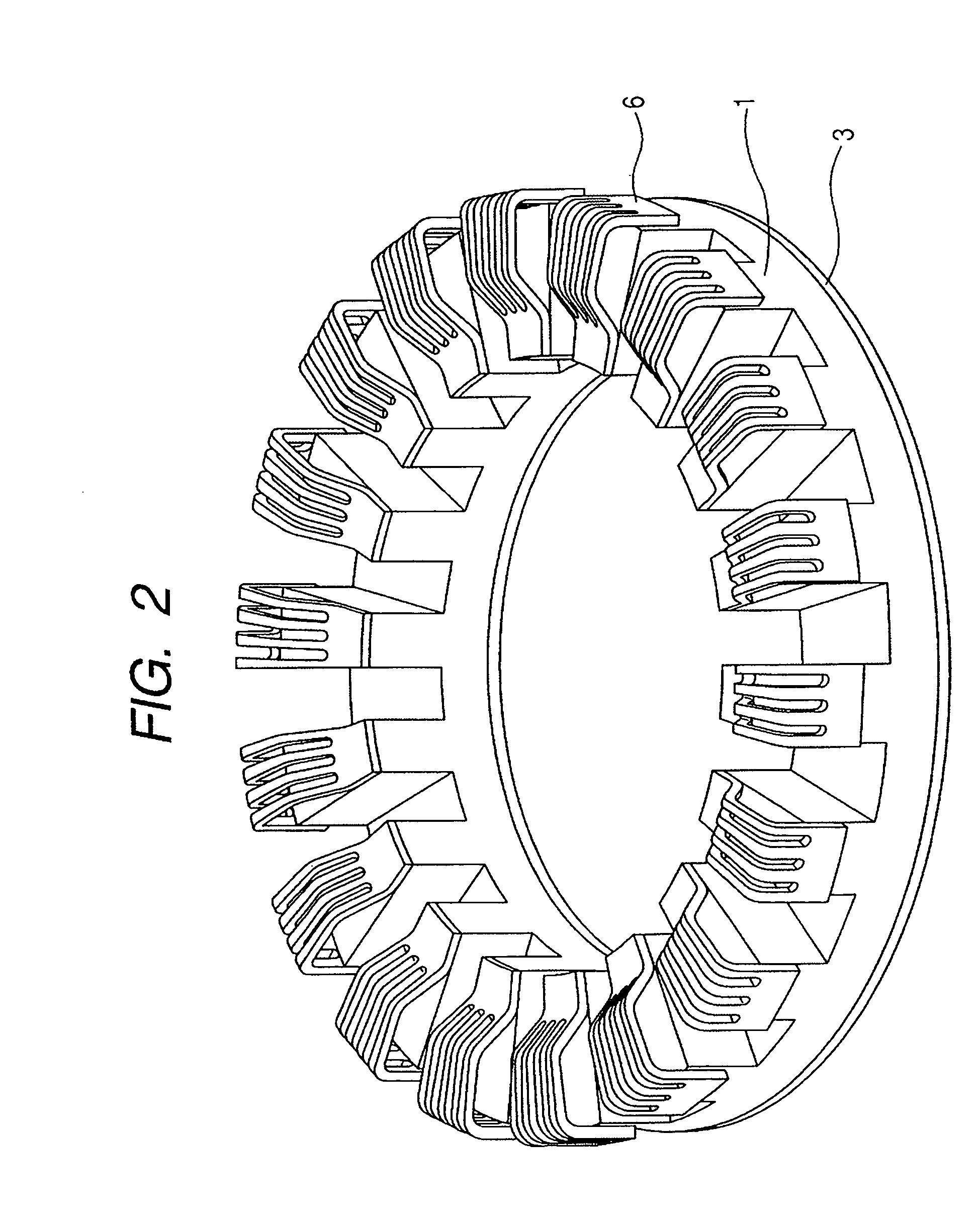
[0047]In FIG. 1, the vibration wave motor is formed into a circular ring shape, and is provided with a vibration member 1, a piezoelectric element 3, a moving element 5 and a plurality of contact members 6.

[0048]The vibration member 1 is a metallic elastic member having radial projections, and is comprised of vibration expanding portions 1-1 and a vibration member base 1-2. The radial projections are the vibration expanding portions 1-1. The piezoelectric element 3 is an electromechanical energy converting element which converts an electrical amount (voltage) into a mechanical amount (vibration), and is joined to the vibration member 1. A vibration element is constituted by the vibration member 1 and the piezoelectric element 3. Each contact member 6 is made by the press working of a sheet, and a plur...

second embodiment

[0071]A second embodiment of the present invention differs from the above-described first embodiment in that the contact portion is of such structure as shown in FIG. 6. The other elements (the vibration member 1, the piezoelectric element 3 and the moving element 5) in the present embodiment are the same as the corresponding ones of the above-described first embodiment and therefore need not be described.

[0072]FIG. 6 is a partly enlarged perspective view of the vibration member and contact portion of a vibration wave motor according to the present embodiment.

[0073]In FIG. 6, a contact member 16 is provided with connecting portions 16b-1 to 16b-5 having opposite-ends fixed beam structure divided into a plurality (five in the present embodiment).

[0074]Of the connecting portions 16b-1 to 16b-5, the width of the connecting portion 16b-3 located at the center is widest, and the widths of the connecting portion 16b-1 and the connecting portion 16b-5 located at the opposite ends are narro...

third embodiment

[0080]A third embodiment of the present invention differs from the above-described first embodiment in that the contact portion is of such structure as shown in FIG. 8. The other elements (the vibration member 1, the piezoelectric element 3 and the moving element 5) in the present embodiment are the same as the corresponding ones of the above-described first embodiment and therefore need not be described.

[0081]FIG. 8 is a partly enlarged perspective view of the vibration member and contact portion of a vibration wave motor according to the present embodiment.

[0082]In FIG. 8, a contact member 26 is provided with a fixed portion 26a, connecting portions 26b-1 to 26b-4 having opposite-ends fixed beam structure divided into a plurality (four in the present embodiment), and four leg portions 26c for connecting the fixed portion 26a and the connecting portions 26b-1 to 26b-4 together.

[0083]The bases (the side connected to the fixed portion 26a) of the leg portions 26c corresponding to the...


PUM


Abstract

This invention provides a vibration wave driving apparatus which makes it possible to reduce the localized abrasion of a contact member, and reduce the deterioration of performance due to long-term driving. This vibration wave driving apparatus has a contact member which is provided with fixed portions fixed to the lengthwise opposite end portions of the vibration expanding portion of the vibration member, and a connecting portion integrally connecting the two fixed portions together and having opposite ends fixed beam structure divided into a plurality.

Description

BACKGROUND OF THE INVENTION[0001]1. Field of the Invention[0002]This invention relates to a vibration wave driving apparatus applied to a so-called vibration wave motor which generates vibration on an elastic member by an electromechanical energy converting element for converting an electrical amount (voltage) into a mechanical amount (vibration), and moves a contact member contacting with the elastic member.[0003]2. Related Background Art[0004]There has heretofore been a vibration wave motor for driving a moving element by vibration generated by a vibration element. The vibration wave motor produces a force continuously driving the moving element, by the use of mechanical vibration generated by the vibration element. Therefore, a contact member disposed between the vibration element and the moving element repeats contact with and separation from the vibration element while being deformed following the vibration of the vibration element, thereby producing a driving force. A vibratio...

Claims


Application Information

Patent Timeline
Patent Type & Authority Patents(United States)
IPC IPC(8): H02N2/00
CPCH02N2/163H02N2/0065
Inventor FUJIMOTO, KOSUKE
Owner CANON KK
Why Eureka
Try Eureka