Microwave generator

a generator and micro-wave technology, applied in the direction of electrical/magnetic/electromagnetic heating, transit-tube circuit elements, structural circuit elements, etc., can solve the problems of adversely affecting high-voltage dielectric strength, and achieve the effect of reducing dielectric strength

Active Publication Date: 2008-10-21
DIEHL BGT DEFENCE GMBH & CO KG
View PDF9 Cites 6 Cited by
  • Summary
  • Abstract
  • Description
  • Claims
  • Application Information

AI Technical Summary

Benefits of technology

[0010]The object of the invention is to provide a microwave generator of the kind set forth in the introductory portion of this specification, which, instead of a laterally parallel arrangement, permits an axially linear arrangement of the microwave generator with an associated high voltage source, without a reduction in dielectric strength.
[0011]The microwave generator according to the invention has the advantage that the high voltage source can be arranged in axially aligned successive relationship with the microwave generator so that it is possible to implement a structure which is cylindrical in a bar shape, and the resonator spark gap is integrated into the axially aligned feed.

Problems solved by technology

The interior of the housing sleeve, apart from the two electrodes, does not contain any further parts and components, which could adversely affect high voltage dielectric strength.

Method used


Image

  • Microwave generator
  • Microwave generator

Examples


Embodiment Construction

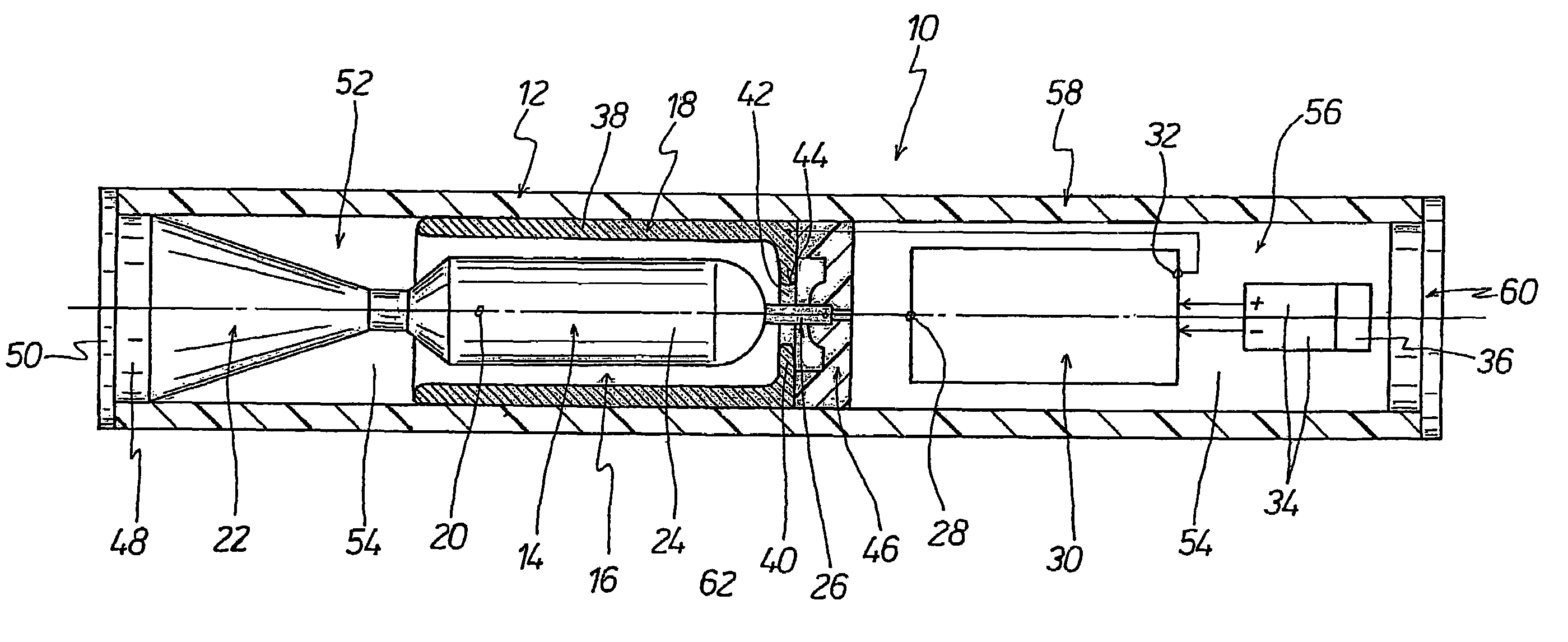
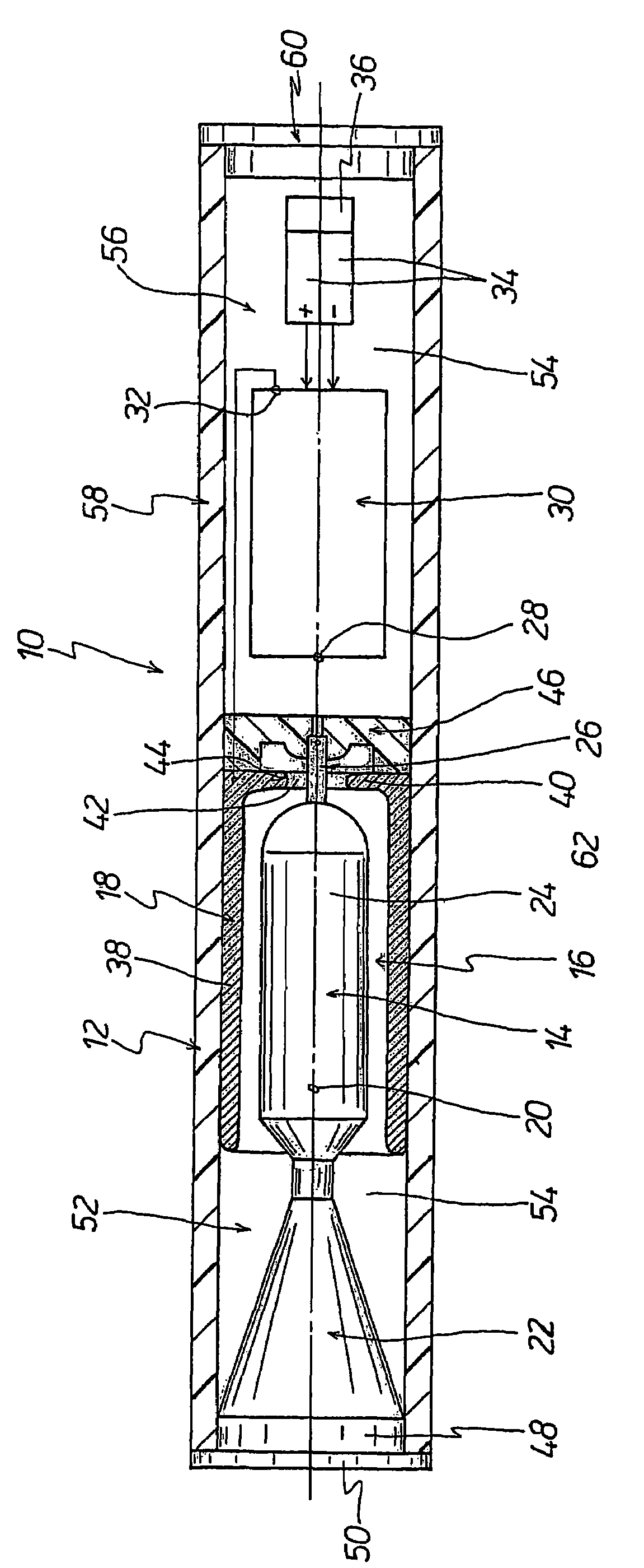
[0013]The FIGURE shows a configuration of the microwave generator 10, which in a housing sleeve 12 has a central electrode 14 and an external electrode 18, which coaxially encloses the central electrode 14 along an axially extending resonator portion 16. The central electrode 14 and the external electrode 18 are of a rotationally symmetrical configuration around a central longitudinal axis 20.

[0014]A radiating element 22 adjoins the central electrode 14 at the front end, in one piece in respect of the material thereof, with the radiating element 22 being enlarged in a tapering configuration forwardly away from the central electrode 14.

[0015]The central electrode 14 has a lobe portion 24 which defines the resonator portion 16 and from which the radiating element 22 projects at the front end. At the rear end a connection element 26 extends away from the lobe portion 24, that is to say it extends in the direction of the central longitudinal axis 20. The connection element 26 serves for...


PUM


Abstract

A microwave generator having a central electrode (14) which at the front end has a radiating element (22) and an external electrode (18) which coaxially surrounds the central electrode (14) along an axially extending resonator portion (16), wherein the two electrodes (14 and 18) are of a rotationally symmetrical configuration and define a spark gap (62) which sparks across when a high voltage is applied and radiates microwaves by way of the resonator portion (16) and the radiating element (22) of the central electrode (14). The spark gap (62) is in the form of an annular spark gap, which is determined by a connection element (26) which projects at the rear end axially centrally away from the central electrode (14) and an annular edge (44) of the external electrode (18), the edge being provided coaxially with respect to the connection element (26). The central electrode (14) and the external electrode (18) are arranged in a housing sleeve (12) of an electrically insulating material. The housing sleeve (12) preferably has an extension (58) defining a space (56) in which there is arranged a high voltage source (30), which is electrically conductively connected to the electrodes (14 and 18) of the microwave generator (10)

Description

BACKGROUND OF THE INVENTION[0001]1. Field of the Invention[0002]The invention concerns a microwave generator comprising two coaxially arranged electrodes which are provided in a housing and which are separated by way of a spark gap, which sparks across when a high voltage is applied for the radiation of microwaves.[0003]The functioning of such a microwave generator is based on a high voltage source being short-circuited across a spark gap and thus discharged. The high voltage source can have a capacitor array which is charged up in parallel on the basis of the principle of the Marx surge voltage circuit and which is then connected in series. As an alternative to using a Marx surge voltage circuit it is also possible to employ an explosive-operated high voltage generator, which, in comparison with conventional high voltage generators, can provide a single high voltage pulse with an extremely high level of pulse energy.[0004]As a consequence of the short-circuiting of the high voltage...

Claims


Application Information

Patent Timeline
Patent Type & Authority Patents(United States)
IPC IPC(8): H01T2/00
CPCH01T9/00F41H13/0068H03B11/02
Inventor DOMMER, JOSEFSTAINES, GEOFFREY
Owner DIEHL BGT DEFENCE GMBH & CO KG
Why Eureka
Try Eureka