Separable electrical connector assembly

Inactive Publication Date: 2004-09-30
THOMAS & BETTS INT INC
View PDF70 Cites 7 Cited by
  • Summary
  • Abstract
  • Description
  • Claims
  • Application Information

AI Technical Summary

Benefits of technology

0011] It is an object of the invention to provide separable electrical connectors, which upon

Problems solved by technology

During initial movement of the loadbreak connectors in the disassembly operation, the volume of air in the elbow cavity increases but is sealed off at the elbow cuff resulting in a decrease in pressure within the cavity.
Although this is a transient condition, it occurs at a critical point in the disassembly operation and can result in dielectric breakdown of the opening interface causing a flashover or arc to ground.
The lower pressure in the cavity reduces the dielectric strength of the air along the connection interface possibly resulting in flashover.
One drawback with loadbreak connectors of the prior art is

Method used


Image

  • Separable electrical connector assembly
  • Separable electrical connector assembly
  • Separable electrical connector assembly

Examples


Example

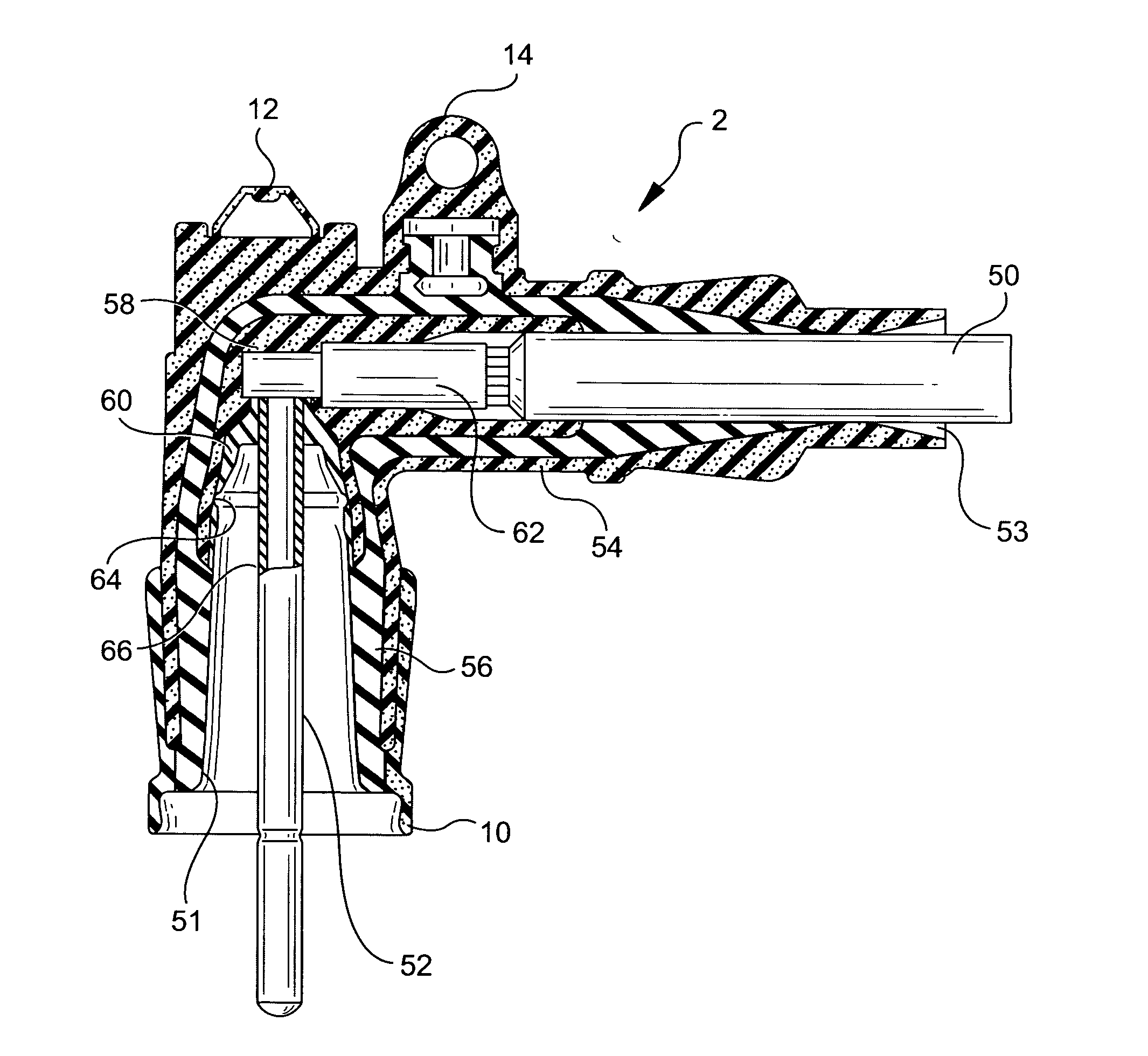
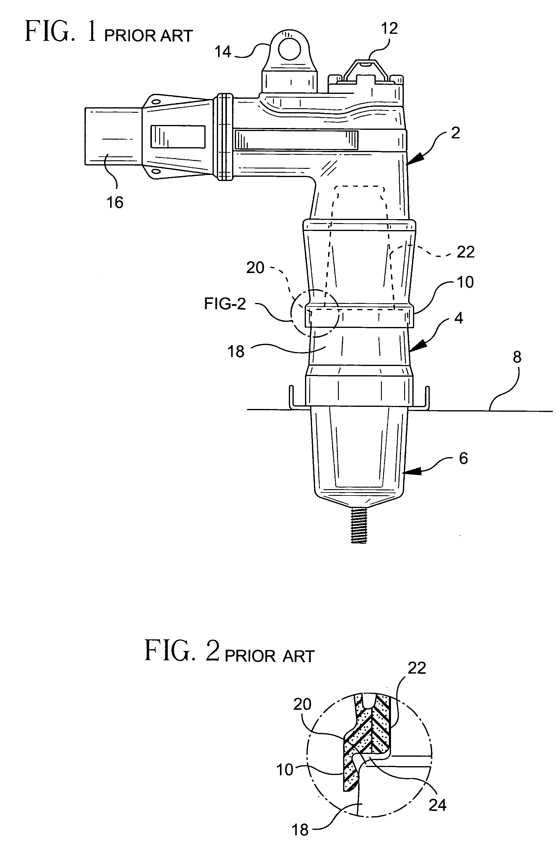
[0049] Referring to FIGS. 1 and 2, prior art loadbreak connectors are illustrated. In FIG. 1, a power cable elbow connector 2 is illustrated coupled to a loadbreak bushing insert 4 which is seated in a universal bushing well 6. The bushing well 6 is seated on an apparatus face plate 8. The power cable elbow connector 2 includes a first end adapted for receiving a loadbreak bushing insert 4 and having a flange or elbow cuff 10 surrounding the open receiving end thereof. The power cable elbow connector also includes an opening eye 12 for providing hot-stick operation and a test point 14 which is a capacitively coupled terminal used with appropriate voltage sensing devices. A power cable receiving end 16 is provided at the opposite end of the power cable elbow connector and a conductive member extends from the receiving end to the bushing insert receiving end for connection to a probe insertion end of the bushing insert.

[0050] Referring still to FIGS. 1 and 2, the loadbreak bushing ins...


PUM

PropertyMeasurementUnit
Coloraaaaaaaaaa
Electric potential / voltageaaaaaaaaaa
Frictionaaaaaaaaaa

Abstract

A method for forming a separable electrical connector having an electrical interface surface includes the steps of molding an interface shell from a thermoplastic, placing the interface shell against an electrical interface portion of a mold cavity and molding a housing within the mold cavity. When placed in the mold cavity, the interface shell provides a barrier to the mold cavity interface portion, wherein the housing is isolated from the electrical interface potion of the mold cavity by the interface shell. The shell has an inner surface and an outer surface and the housing is bonded to one of the inner and outer surfaces, wherein the other of the inner and outer surfaces of the shell defines the electrical interface surface of the electrical connector.

Description

CROSS-REFERENCE TO RELATED U.S. APPLICATIONS[0001] This application is a continuation-in-part of U.S. application Ser. No. 10 / 186,843, filed on Jul. 1, 2002, which is a continuation-in-part of U.S. application Ser. No. 09 / 715,571, filed on Nov. 17, 2000, now U.S. Pat. No. 6,585,531, which is a continuation of U.S. application Ser. No. 09 / 287,915, filed on Apr. 7, 1999, now U.S. Pat. No. 6,168,447, which is a continuation-in-part of Ser. No. 08 / 902,749, filed on Jul. 30, 1997, now U.S. Pat. No. 5,957,712.[0002] 1. Field of the Invention[0003] The present invention relates to separable electrical connectors and more particularly to improvements in manufacturing separable electrical connectors, such as loadbreak connectors and deadbreak connectors, wherein a sleeve of low coefficient of friction material is provided during a molding process to protect the critical electrical interfaces of the connector from contamination. The sleeve further provides for ease of connection and disconnec...

Claims


Application Information

Patent Timeline
IPC IPC(8): B29C45/14H01R13/504H01R13/52H01R13/53H01R13/629H01R13/648H01R33/76H01R43/00H01R43/26
CPCH01R13/5216Y10T29/49218H01R13/53H01R13/629H01R13/648H01R24/20H01R33/7678H01R43/26H01R2101/00Y10S439/921Y10T29/49224Y10T29/49204Y10T29/49208Y10T29/4922H01R13/5221G02F1/1309G02F2203/69
Inventor BORGSTROM, ALAN D.STEPNIAK, FRANK M.
Owner THOMAS & BETTS INT INC
Why Eureka
Try Eureka