Signal processing system

a signal processing and signal technology, applied in the field of signal processing systems, can solve the problems of increasing the complexity of motion compensation in real-world images, the inability to implement motion compensation in an ideal manner, and the bandwidth of the generated motion vectors can also be significan

Active Publication Date: 2008-10-21
GEORGIA TECH RES CORP
View PDF11 Cites 11 Cited by
  • Summary
  • Abstract
  • Description
  • Claims
  • Application Information

AI Technical Summary

Problems solved by technology

An added level of complexity occurs during motion compensation in real-world images such as those encountered in MPEG implementations, because moving objects do not necessarily maintain their appearance as they move.
Consequently, motion compensation cannot be implemented in an ideal manner, and supplementary information related to the picture has to be provided to the decoder.
Unfortunately, while the bandwidth of the picture residual may be optimized by this approach, the bandwidth of the generated motion vectors can also turn out to be significant.
The minimization process to determine the optimal values of R and D for various values of λ can turn out to be computationally extensive, as well as expensive, if each and every encoding mode as well as motion estimation / compression process has to be evaluated using the equation above.
Consequently, while several solutions currently exist to implement rate-distortion theory in macroblock mode selection as well as in motion estimation schemes, these solutions suffer from sub-optimal results and / or are computationally complex.

Method used


Image

  • Signal processing system
  • Signal processing system
  • Signal processing system

Examples


Embodiment Construction

[0023]While the description below refers to certain exemplary embodiments, it is to be understood that the invention is not limited to these particular embodiments. On the contrary, the intent is to cover all alternatives, modifications and equivalents included within the spirit and scope of the invention as defined by the appended claims. Also, the terminology used herein is for the purpose of description and not of limitation.

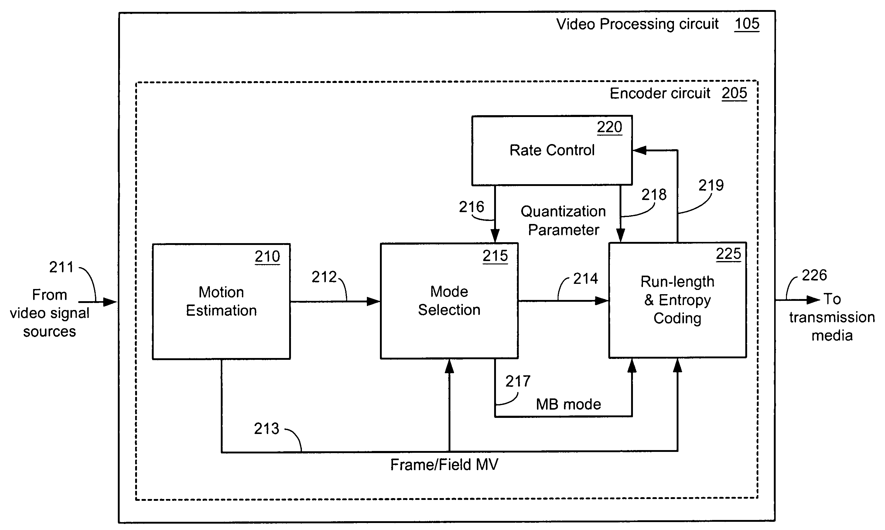
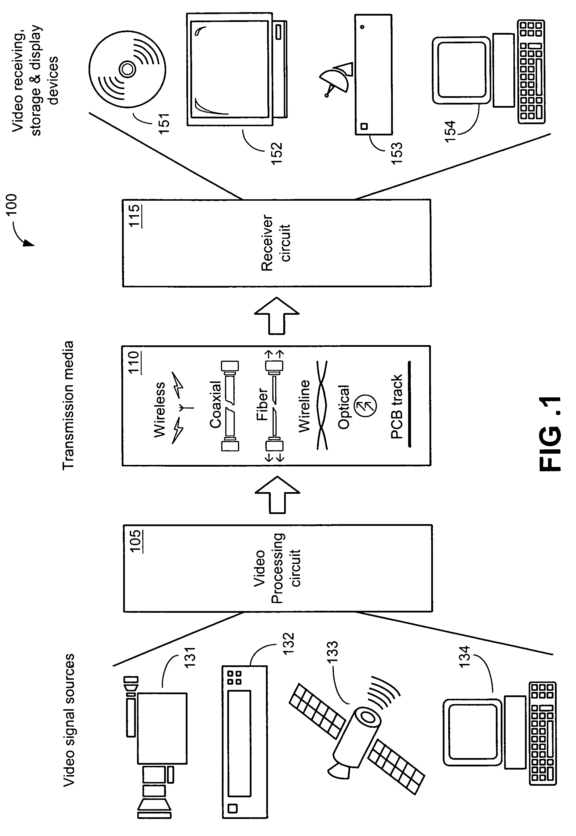
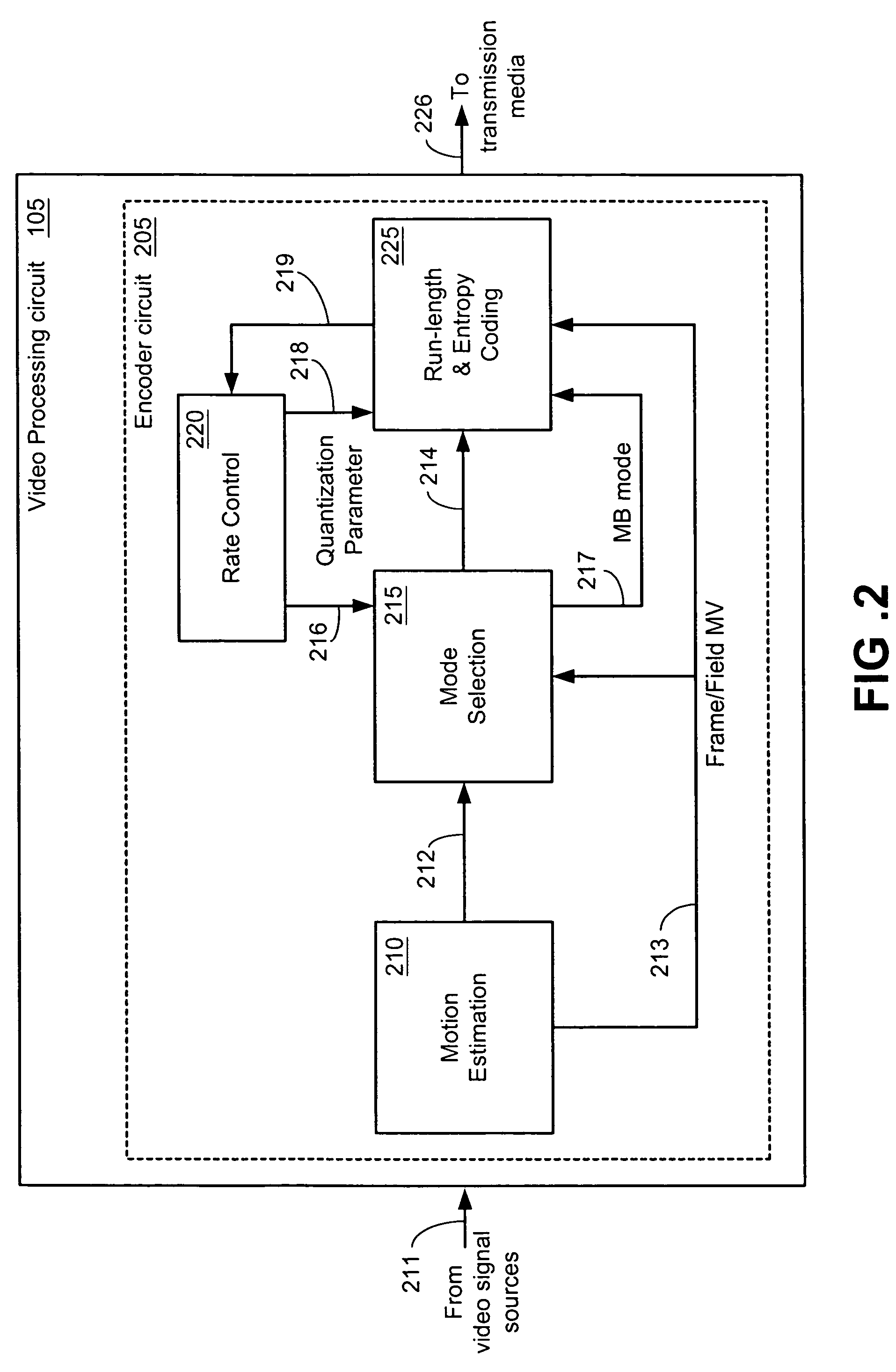
[0024]FIG. 1 illustrates a video system 100 comprising a video processing circuit 105, a transmission media 110, and a receiver circuit 115. Video system 100 is representative of several signal processing systems where signal compression and / or signal encoding processes are employed. Some examples of such systems include television systems, satellite systems, digital video disk (DVD) players, cable television systems, and computer systems. Transmission media 110 encompasses several forms of signal-carrying media, including but not limited to, wireless links, ...


PUM


Abstract

Methods and systems are disclosed for a video system. In a first exemplary embodiment, the video system comprises a video processing circuit that receives a picture and provides video compression by using an optimal macroblock mode of operation, the optimal macroblock mode of operation being identified by processing at least one macroblock of the picture, the processing being performed independent of other macroblocks contained in the picture. Additionally, the video processing circuit comprises a mode selection circuit that identifies the optimal macroblock mode of operation by using a rate-distortion model. The rate-distortion model incorporates an overall macroblock mode distortion D that is defined as the sum of DAC a distortion due to AC coefficients, and DDC a distortion due to DC coefficients.

Description

CROSS REFERENCE TO RELATED APPLICATIONS[0001]This application claims the benefit of U.S. Provisional Patent Application Ser. No. 60 / 426,163, filed Nov. 14, 2002, which is incorporated herein by reference in its entirety.FIELD OF THE INVENTION[0002]The present invention generally relates to the field of signal processing systems. More specifically it relates to video compression and encoding systems.BACKGROUND[0003]Large bandwidth systems, such as video processing systems, strive to obtain high compression ratios by eliminating spatial and temporal redundancies in transmitted pictures. Spatial redundancy refers to redundant video information that is present within a single picture. One example of spatial redundancy can be found in the repeated pixel values that are present inside a single picture of a large expanse of blue sky. Temporal redundancy, on the other hand, refers to redundant video information that is present in successively occurring pictures where certain parts of the pi...

Claims


Application Information

Patent Timeline
Patent Type & Authority Patents(United States)
IPC IPC(8): H04N7/12H04B1/66H04N11/02H04N11/04H04NH04N7/26H04N7/32
CPCH04N19/176H04N19/147H04N19/99H04N19/137H04N19/103
Inventor ALTUNBASAK, YUCELKIM, HYUNGJOON
Owner GEORGIA TECH RES CORP
Why Eureka
Try Eureka