Pneumatic tire

a pneumatic tire and tire body technology, applied in the field of pneumatic tires, can solve the problems of large widthwise shearing strain produced in the belt, easy separation failure, etc., and achieve the effects of suppressing uneven wear of the tread shoulder portion, small uneven wear, and inferior production

Inactive Publication Date: 2008-10-28
BRIDGESTONE CORP
View PDF13 Cites 8 Cited by
  • Summary
  • Abstract
  • Description
  • Claims
  • Application Information

AI Technical Summary

Benefits of technology

[0012]As previously mentioned, when the tire having the circumferential strengthening layer rides on the projection such as stones or the like during the running, since the bending rigidity of the circumferential strengthening layer in the widthwise direction is small, the belt and the circumferential strengthening layer are largely deformed in a concave form starting from the side edge of the circumferential strengthening layer, and as a result, the widthwise shearing strain produced in the belt becomes large and there is a problem that separation failure is easily caused at each end of the belt.
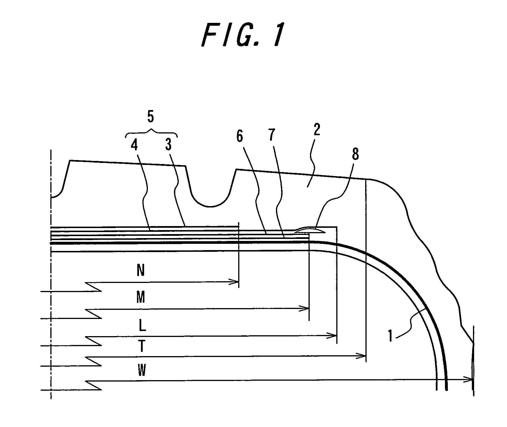
[0026]In this case, the effect of suppressing the uneven wear of the tread shoulder portion by the belt layer located at the inner peripheral side can be guaranteed more surely. When the width of the belt layer located at the inner peripheral side is less than 85% of the treading face width, the effect of suppressing the uneven wear becomes small, while when it exceeds 105%, since it is required to curve the belt layer along the curved portion of the tread shoulder portion, there is a fear of causing the inferior production, and if cut failure is caused in a buttress portion, there is a fear of exposing the belt to easily cause troubles.

Problems solved by technology

As previously mentioned, when the tire having the circumferential strengthening layer rides on the projection such as stones or the like during the running, since the bending rigidity of the circumferential strengthening layer in the widthwise direction is small, the belt and the circumferential strengthening layer are largely deformed in a concave form starting from the side edge of the circumferential strengthening layer, and as a result, the widthwise shearing strain produced in the belt becomes large and there is a problem that separation failure is easily caused at each end of the belt.

Method used


Image

  • Pneumatic tire
  • Pneumatic tire
  • Pneumatic tire

Examples


examples

[0037]For the purpose of evaluating the belt durability and resistance to uneven wear in the heavy duty pneumatic tire according to the invention, each of heavy duty pneumatic tires with a low aspect ratio having tire sizes of 315 / 60 R22.5, 385 / 55 R22.5, 445 / 50 R22.5, 435 / 45 R22.5 and 495 / 40 R22.5 is mounted on the respective approved rim and filled with an air pressure of 900 kPa, which is mounted on a test vehicle and run over 100,000 km, and thereafter the presence or absence of the occurrence of crack in the belt portion and the occurrence of uneven wear in the tread shoulder portion are investigated. The results are shown in Table 1.

[0038]

TABLE 1Width ofWidth ofDistanceinnerouterbetweenWidth ofperipheralperipheralWidth of innercircumferentialcircumferentialside beltside beltperipheralstrengtheningBeltResistance toCut resistancestrengtheninglayer / tirelayer / tireside beltlayer and innerdurabilityuneven wear(presence orAspectlayer / tiresectionsectionlayer / width ofperipheral side(pre...


PUM

PropertyMeasurementUnit
inclination angleaaaaaaaaaa
thicknessaaaaaaaaaa
thicknessaaaaaaaaaa

Abstract

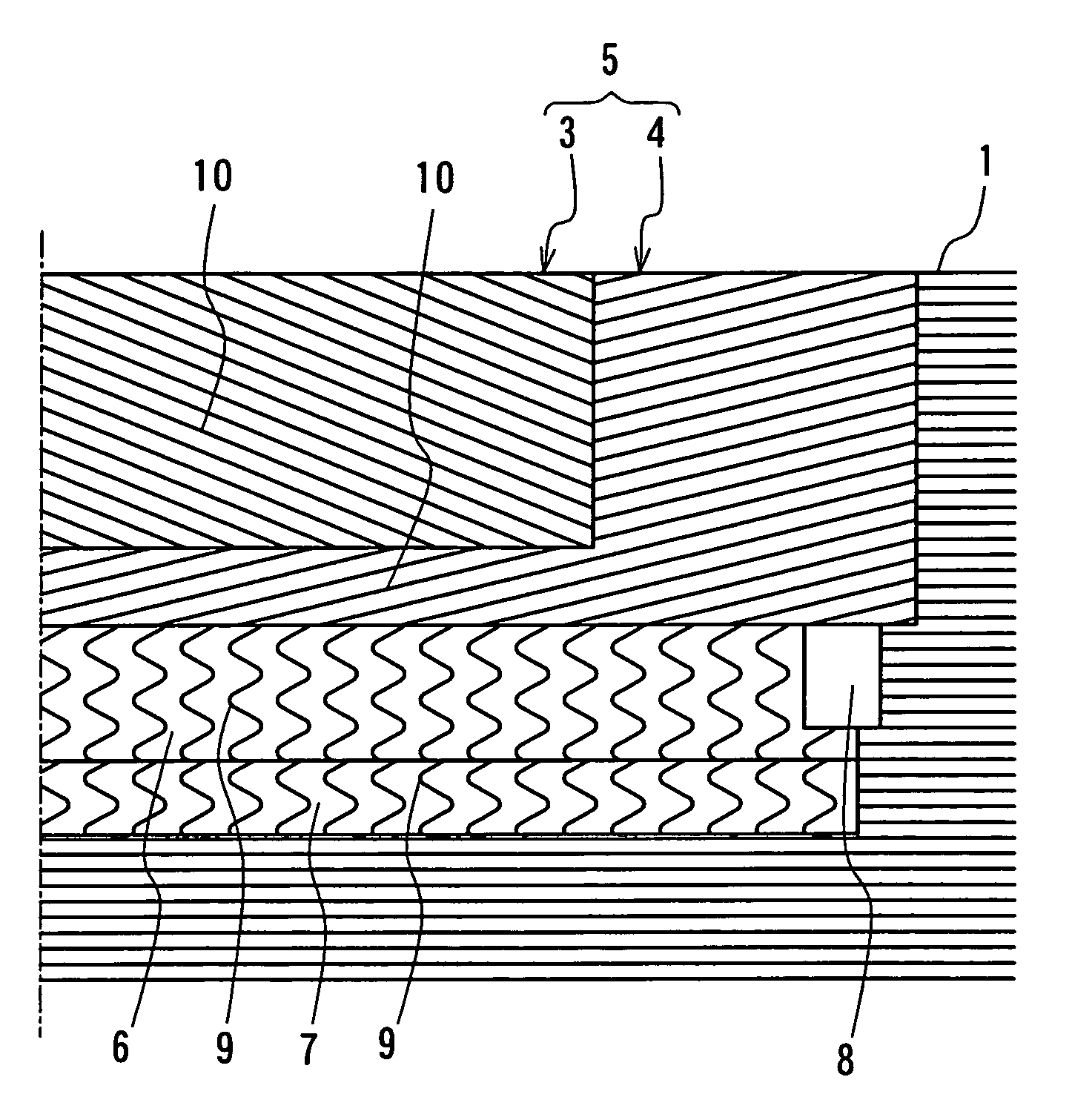
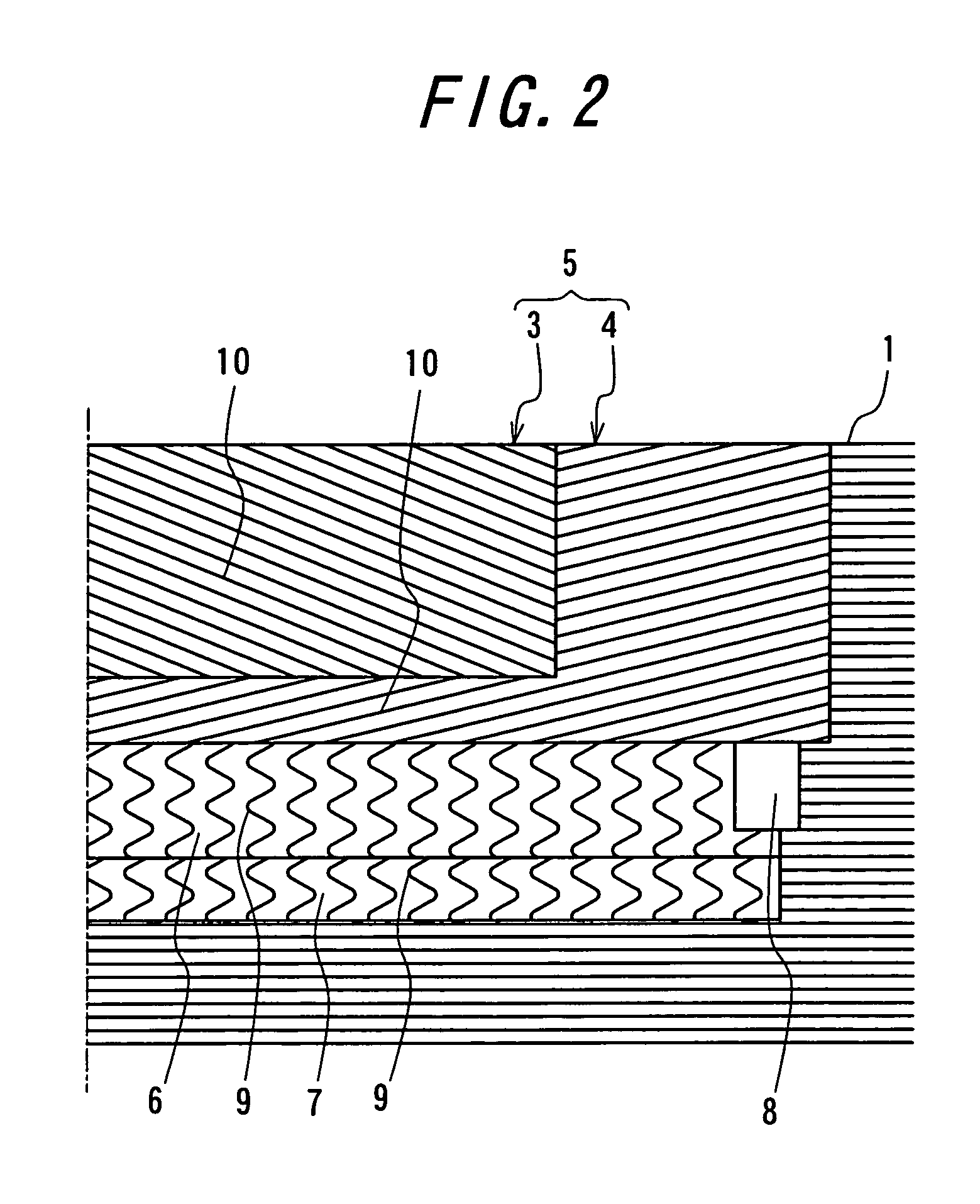
A pneumatic tire comprises a carcass 1 comprised of one or more carcass plies toroidally extending between a pair of bead portions, a tread rubber 2 arranged at an outer peripheral side of a crown portion of the carcass 1, a belt 5 arranged between the tread rubber 2 and the carcass 1 and comprised of two belt layers 3, 4, cords 10 of which layers being crossed with each other and extending in an inclination angle of 45-80° with respect to a circumferential direction of the tire, and one or more circumferential strengthening layers 6, 7 arranged at an inner peripheral side of the belt 5 and containing wavy or zigzag cords 9 extended substantially in the circumferential direction of the tire, in which a width L of a belt layer 7 located at the inner peripheral side is made larger than a width M of the circumferential strengthening layer and a width N of a belt layer located at the outer peripheral side is made smaller than the width M of the circumferential strengthening layer.

Description

TECHNICAL FIELD[0001]This invention relates to a pneumatic tire having improved durability and resistance to uneven wear and mainly suitable for heavy duty vehicles such as truck, bus and the like.BACKGROUND ART[0002]In the heavy duty pneumatic tire, a belt is generally arranged on an outer peripheral side of a crown portion of a carcass for strengthening a tread portion. As the belt is mainly used a cross belt comprised of plural belt layers, cords of which layers being crossed with each other, or a slant belt comprised of one belt layer containing cords inclined in one direction with respect to a circumferential direction of the tire.[0003]When an air pressure is filled in such a pneumatic tire, the hoop effect of the belt becomes smaller in a shoulder portion of the tread positioning cut ends of the belt cords than a central portion of the tread, so that the size growing amount of the belt at the tread shoulder portion becomes larger than that at the tread central portion. As a r...

Claims


Application Information

Patent Timeline
Patent Type & Authority Patents(United States)
IPC IPC(8): B60C9/22B60C9/18B60C9/20B60C9/28
CPCB60C9/20B60C9/28Y10T152/10783
Inventor YAMANAKA, TAKAYA
Owner BRIDGESTONE CORP
Why Eureka
Try Eureka