Splicing device to join together two web materials, unwinding device comprising said splicing device

a technology of splicing device and web material, which is applied in the direction of lamination, projectors, cameras, etc., can solve the problems of complex device, inability to reach the high operating speed currently required for these devices, and inability to meet the high operating speed required for these devices

Active Publication Date: 2008-10-28
FOSBER
View PDF16 Cites 28 Cited by
  • Summary
  • Abstract
  • Description
  • Claims
  • Application Information

AI Technical Summary

Benefits of technology

[0012]The object of the present invention is to produce a splicing device that, starting from the description in EP-A-1.422.175, obtains further advantages in terms of efficiency and constructional simplicity.
[0014]The use of a common control member makes it possible to produce an essentially symmetrical splicing device, that is, with two upper half-heads disposed symmetrically with respect to a common axis of oscillation for the two moving units carrying the cutting members. The two lower half-heads, cooperating with the upper half-heads may also be produced symmetrically to each other. The splicing device may have a configuration wherein the lower half-heads are fixed and the upper half-heads are moving on a common carriage or slide. However, in a particular embodiment the lower half-heads are carried by slides integral with arms for supporting and handling the reels.

Problems solved by technology

The device described in U.S. Pat. No. 3,858,819 is complex and is unable to reach the high operating speeds currently required for these devices.
This device is also complex due to the need to provide several actuators to control the various members of the splicing device.
The speeds that can be reached are limited.

Method used


Image

  • Splicing device to join together two web materials, unwinding device comprising said splicing device
  • Splicing device to join together two web materials, unwinding device comprising said splicing device
  • Splicing device to join together two web materials, unwinding device comprising said splicing device

Examples


Embodiment Construction

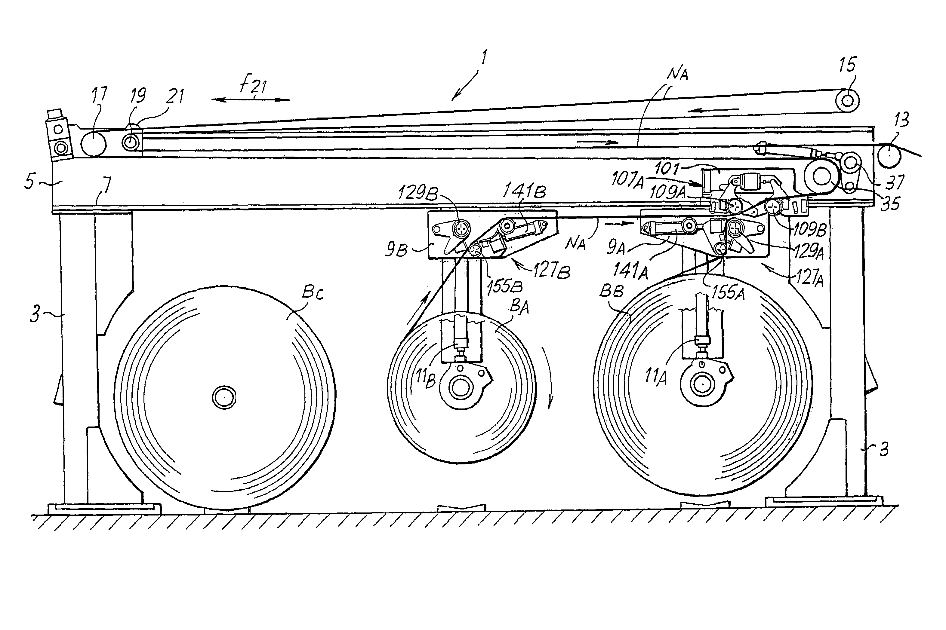
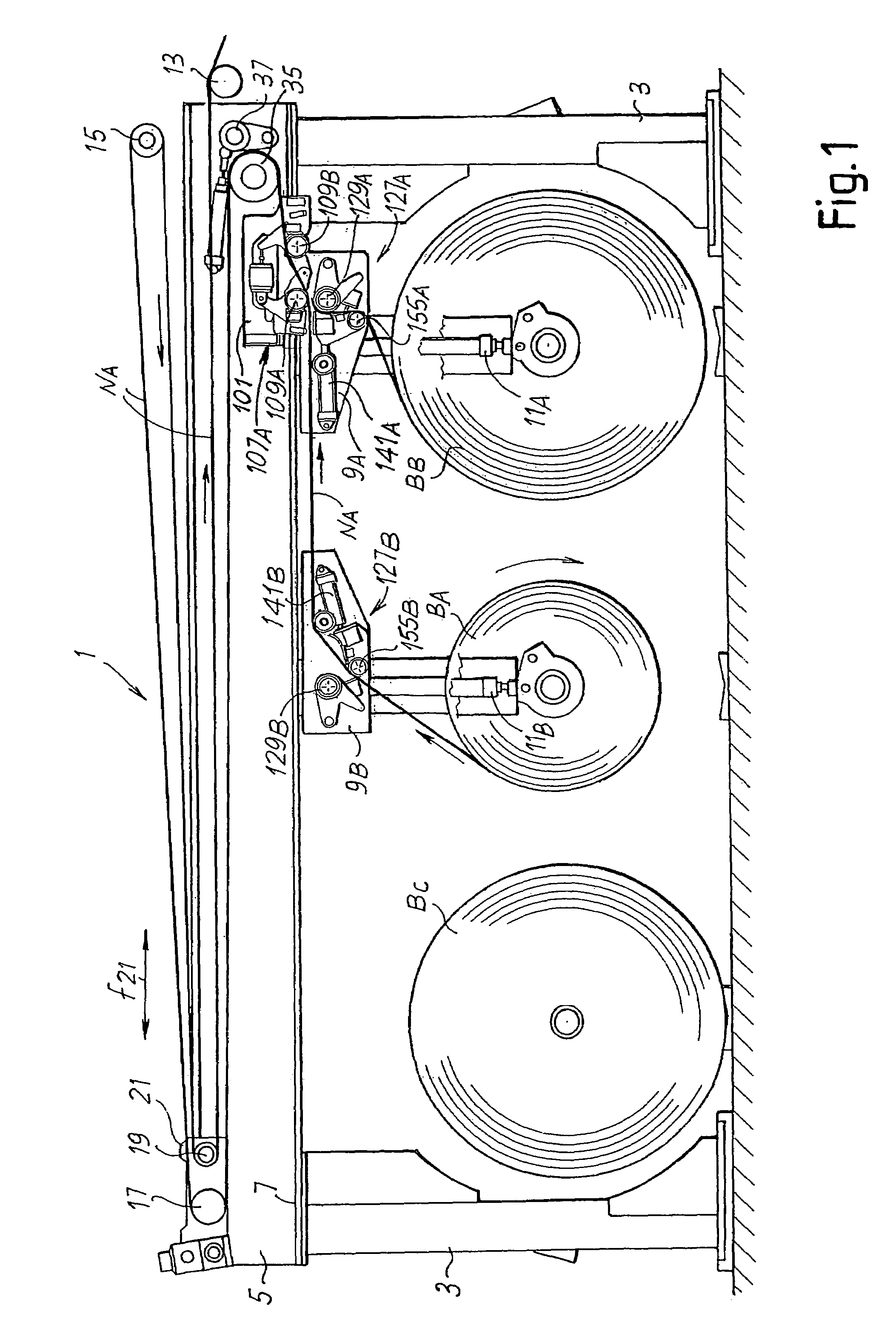
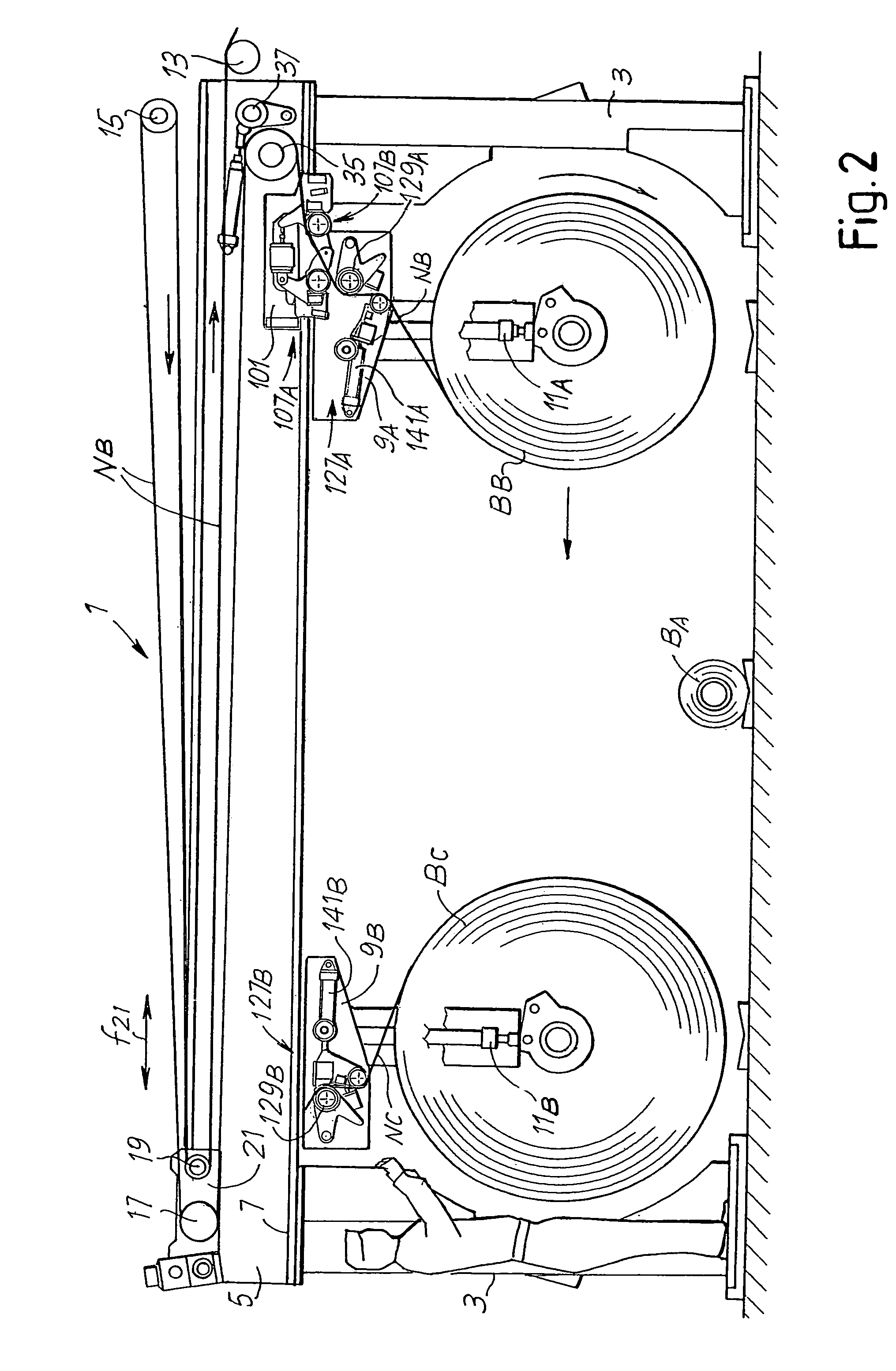
[0031]FIGS. 1 to 4 show, in different operating steps, an unwinding device to feed a web material to a processing line downstream, not shown. A splicing device according to the invention is combined with the unwinding device. The unwinding device may typically be inserted in a production line for corrugated cardboard, and the reels unwound thereby may be reels of sheets of cardboard forming the components of the corrugated cardboard.

[0032]The structure of the unwinding device, indicated as a whole with 1, may vary with respect to what is shown, the splicing device of the invention also being suitable to be applied to unwinding devices differing in arrangement. The unwinding device shown herein is of the type described in greater detail in EP-A-1348658.

[0033]In the example illustrated, the unwinding device has a fixed structure with two pairs of uprights 3 (a single upright of each pair being visible in the drawing) and a pair of crosspieces 5 (one of which is visible in the drawing ...


PUM

PropertyMeasurementUnit
pressureaaaaaaaaaa
counter-pressureaaaaaaaaaa
distanceaaaaaaaaaa

Abstract

A splicing device to join a first web material coming from a reel being fed (BA), to a second web material (NB), coming from a reel standing by (BB), comprising two heads (107A, 127A; 107B, 127B), each of which comprises: a roller (129A; 129B) associated with a clamping bar (143A, 145A; 143B, 145B) to hold an initial edge of the second web material (NB); a counter-pressure member (109A; 109B) cooperating with said roller (129A; 129B) to press said first and second web material (NA, NB) against each other; a cutting member (111A; 111B); a moving unit (113A; 113B), on which said counter-pressure member (109A; 109B) and said cutting member (111A; 111B) are carried. A first common control member (121) is provided to cause, by the movement it imparts to the moving unit of one or other head alternately: pinching of the first and second web material between the roller (129A; 129B) and the counter-pressure member (109A; 109B); cutting of the first web material; and release of the second web material.

Description

TECHNICAL FIELD[0001]The present invention relates to a device to join together two webs, for example two sheets of cardboard, to allow continuous feed of a web material wound in reels towards a processing line, for example a machine for producing corrugated cardboard.[0002]The invention also relates to an unwinding device, in which reels of web material are unwound in succession, provided with a splicing device to join a first web material coming from a reel being unwound to the head or initial edge of a second web material coming from a reel standing by.STATE OF THE ART[0003]In many industrial applications, for example, although not exclusively, in the production of corrugated cardboard, a web material from a reel being unwound is fed towards a production line. In the case of corrugated cardboard, for example, the web material is fed to a “single facer” or to a “double facer” to be coupled with other sheets of web material, if necessary after corrugation thereof.[0004]To obtain co...

Claims


Application Information

Patent Timeline
Patent Type & Authority Patents(United States)
IPC IPC(8): B65H21/00B65H19/18B31F5/00B65H19/00
CPCB65H19/1852B65H19/1863Y10T156/12B65H2701/1762
Inventor ADAMI, MAURO
Owner FOSBER
Why Eureka
Try Eureka