Simple creep test device of rocks and test method thereof

A creep test and rock technology, applied in the field of simple rock creep test device, can solve the problems of complex test device system, high cost and high test cost

Inactive Publication Date: 2010-01-06
HENAN POLYTECHNIC UNIV
View PDF0 Cites 20 Cited by
  • Summary
  • Abstract
  • Description
  • Claims
  • Application Information

AI Technical Summary

Problems solved by technology

[0003] For above-mentioned situation, in order to overcome the defect of prior art, the purpose of the present invention is exactly to provide a kind of simple and easy rock creep test device and test method thereof, can effectively overcome test device system complexity, expensive cost, loaded down with trivial details test process, test cost height, So as to effectively solve the problem of rock uniaxial and triaxial tests and obtain stress-strain curves, the technical solution is to include test platform reaction frame, specimen axial pressure actuation system and specimen confining pressure actuation system , the reaction frame of the test platform is composed of the base and the counter-pressure pillar on the base. The upper part of the counter-pressure pillar is equipped with a top beam, and the lower part of the top beam is equipped with a test piece axial pressure actuation system. The external hydraulic control system is connected, and a pressure sensor is installed at the lower part of the axial pressure actuation system of the specimen. The invention is simple in structure, novel and unique, easy to operate, low in cost, and simple in the test process, and can be effectively used for uniaxial and triaxial creep tests of rocks to obtain stress-strain curves, providing scientific basis for engineering construction, economical and Huge social benefits

Method used


Image

  • Simple creep test device of rocks and test method thereof
  • Simple creep test device of rocks and test method thereof
  • Simple creep test device of rocks and test method thereof

Examples


Embodiment Construction

[0010] The specific implementation manners of the present invention will be described in detail below in conjunction with the accompanying drawings.

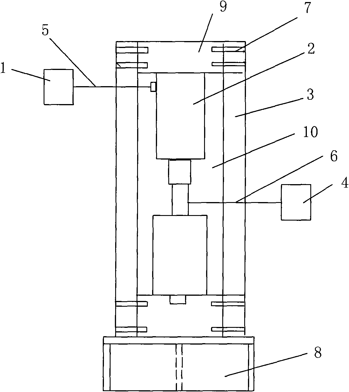
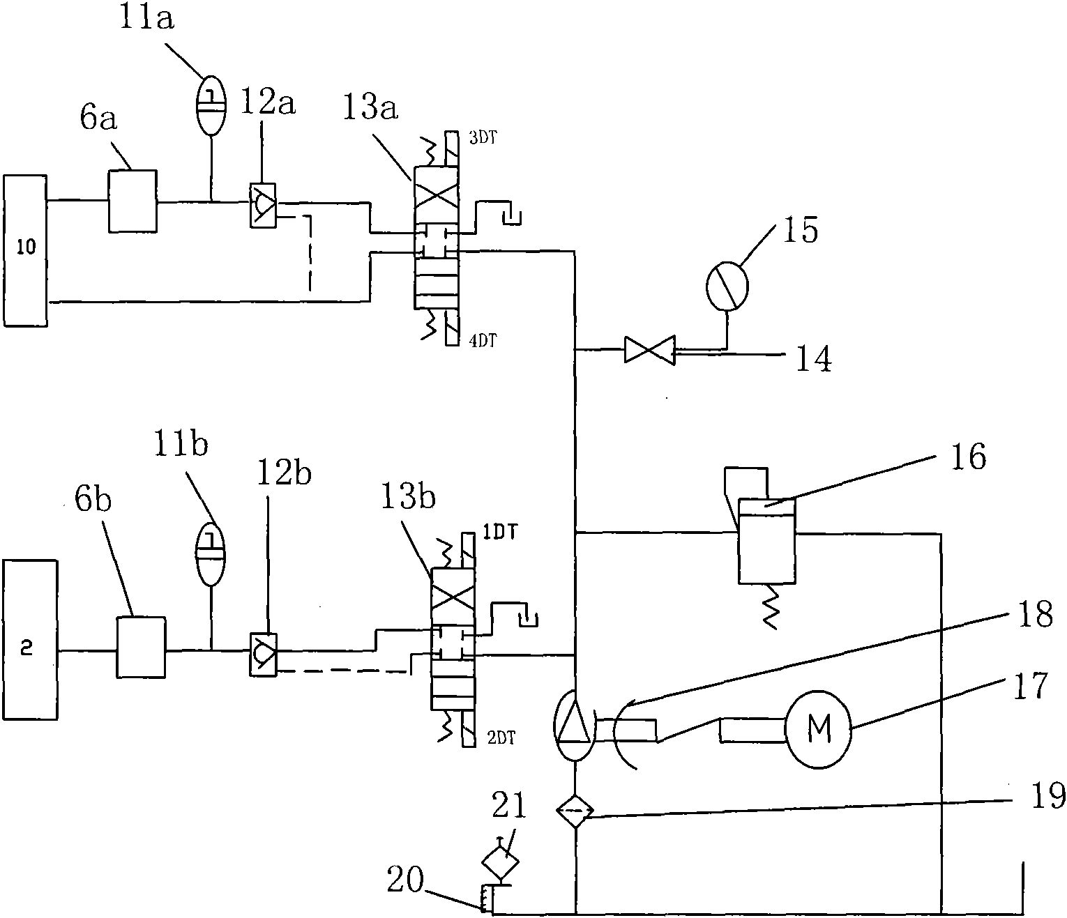
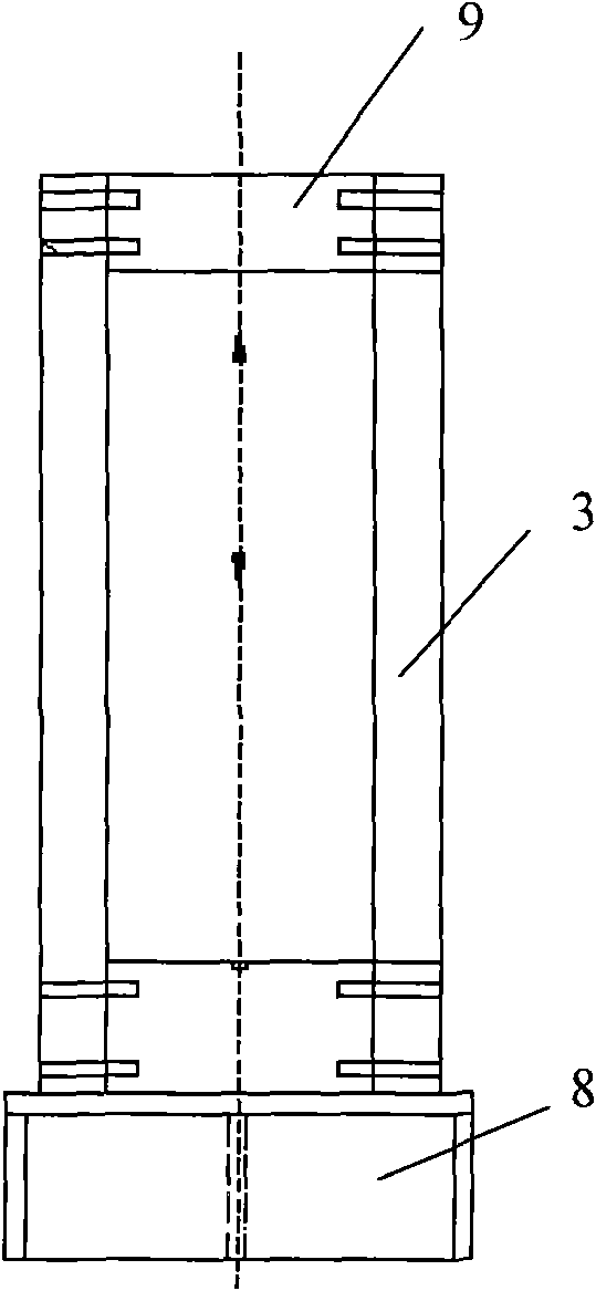
[0011] Depend on Figure 1-5 As shown, the present invention includes a test platform reaction frame, a test piece axial pressure actuation system and a test piece confining pressure actuation system. The test platform reaction force frame is composed of a base 8 and a counter pressure support 3 on the base. The counter pressure support 3. The top beam 9 is installed on the upper part, and the top beam 9 is fixed together with the counter pressure pillar 3 (for the convenience of maintenance, the rivet 7 can be used for fixed connection). The actuating system 2 is connected to the external hydraulic control system 1 through the oil pipeline 5, and a pressure sensor 6 is installed at the lower part of the axial pressure actuating system 2 of the specimen. There is a test piece confining pressure actuation system 10 connected wit...


PUM


Abstract

The invention relates to a simple creep test device of rocks and a test method thereof, which effectively overcome the defects of complex systems, high cost, complicated test processes and high test cost of the test device and effectively solve the problem of obtaining a stress-strain curve in uniaxial and triaxial tests of rocks. The device has the structural characteristics that a reaction frame of a test platform comprises a base and a counter-pressure strut on the base, wherein the upper part of the counter-pressure strut is provided with a top beam; the lower part of the top beam is provided with an axial pressure actuating system of specimens; the axial pressure actuating system of specimens is connected with an external hydraulic control system through an oil conveying pipe; the lower part of the axial pressure actuating system of specimens is provided with a pressure sensor; the pressure sensor is connected with an external automatic data collecting system; and the inside of the counter-pressure strut is a triaxial pressure chamber of a pressure-confined actuating system of specimens. The invention has the advantages of simple structure, novelty, peculiarity, easy operation, low cost and simple test processes, can be effectively used in uniaxial and triaxial creep tests of rocks to obtain the stress-strain curve, provides a scientific basis for engineering construction, and has significant economic and social benefits.

Description

1. Technical field [0001] The invention relates to a rock mechanics experiment device, in particular to a simple rock creep test device (platform) and a test method thereof. 2. Background technology [0002] In engineering practice, creep phenomena such as displacement after the completion of the retaining wall, settlement during tunnel construction, instability and failure of the slope over time, and instability of the coal pillar will be encountered. The deformation increases with time, the strength gradually decreases, and even leads to failure. Creep has attracted widespread attention now. Creep mechanisms have been revealed from various aspects, from on-site creep displacement monitoring, indoor creep experiments to numerical simulations of stability considering creep. On-site monitoring has the disadvantages of high cost, inconvenient data processing, and large external interference. Although the numerical simulation is simple, it needs to establish a creep model, and...

Claims


Application Information

Patent Timeline
Patent Type & Authority Applications(China)
IPC IPC(8): G01N3/28
Inventor 李振华李化敏苏承东韩学锋
Owner HENAN POLYTECHNIC UNIV
Why Eureka
Try Eureka