
Method and system for monitoring environmental conditions

a technology of environmental conditions and monitoring systems, applied in the direction of generators/motors, instruments, heat measurement, etc., can solve the problems of lack of electronic interface, inability to ensure the functionality and state of goods and products, and substantial economic losses

Inactive Publication Date: 2007-02-01
BELLUTECH LLC
View PDF23 Cites 38 Cited by
  • Summary
  • Abstract
  • Description
  • Claims
  • Application Information

AI Technical Summary

Benefits of technology

[0013] In view of the above, it can be seen that the MEMS digital sensing system, sensing method, and fabrication method of this invention are well suited for implementing automated and cost-effective supply chain management by processing the digital outputs of the sensing elements to generate one or more cumulative system outputs, such as cumulative temperature and humidity outputs, and then using an RFID wireless link for transmission of these cumulative outputs to a RFID reader (interrogator). The advantages of the invention can be further realized by fabricating the sensing elements using CMOS-compatible batch fabrication process technologies. By fabricating large arrays of MEMS sensing elements and selecting only certain elements to generate the system output based on the desirable operational characteristics of the selected elements, the present invention enables post-manufacturing sensor testing to be greatly simplified by avoiding the need for post-manufacturing calibration or otherwise adjusting sensing characteristics of individual sensors that tend to deviate from targeted characteristics due to manufacturing process variations and tolerances. Finally, another advantage of the invention is the ability to employ an electronic system architecture that in conjunction with the sensing elements results in ultra-low power operation and extended battery life.
[0014] Other objects and advantages of this invention will be better appreciated from the following detailed description.

Problems solved by technology

In both commercial and military applications, assuring functionality and / or the absence of deterioration, spoilage, etc., is extremely crucial, since otherwise lives could be at risk and substantial economic losses could incur.
However, the functionality and state of goods and products cannot be ensured without continuously monitoring environmental conditions, particularly heat and humidity, and the cumulative effects thereof.
However, significant shortcomings include being typically limited to indicating or recording only maximum (or minimum) temperature or humidity levels.
Furthermore, while sensor labels provide an easily observable visual output, they lack an electronic interface and thus are difficult to deploy in automated supply chain management networks.
However, sensor modules are generally costly, have limited battery lifetime, are excessive in size for many applications, and require an additional (internal or external) software layer to provide a cumulative output.
The high cost of these modules, particularly at an item-level, is a major barrier to their wide use in many applications.

Method used


Image

  • Method and system for monitoring environmental conditions
  • Method and system for monitoring environmental conditions
  • Method and system for monitoring environmental conditions

Examples


Embodiment Construction

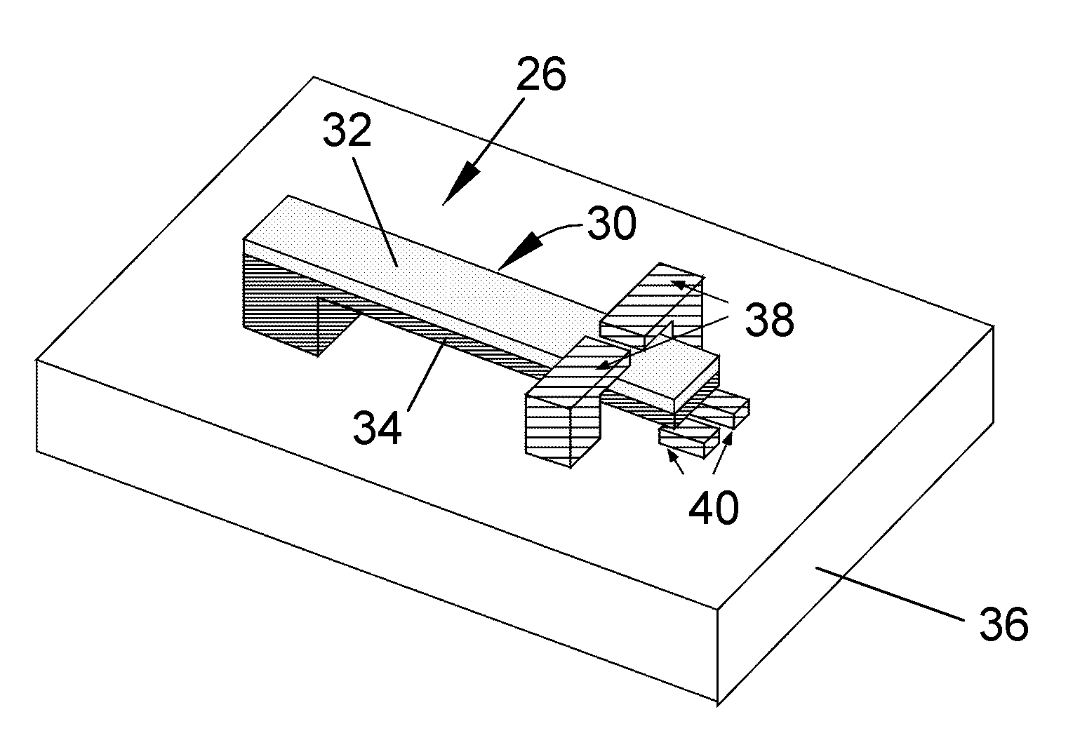
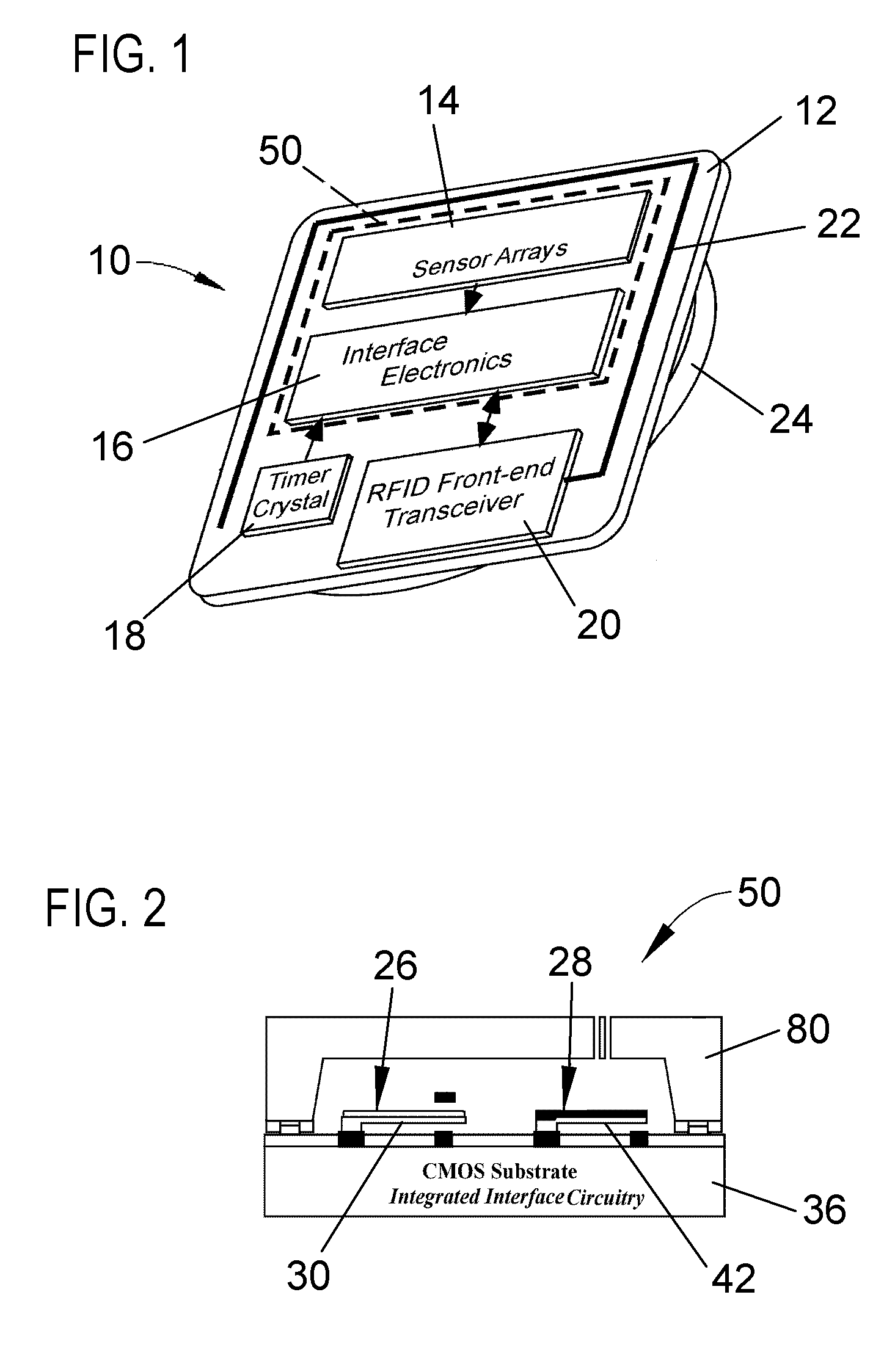
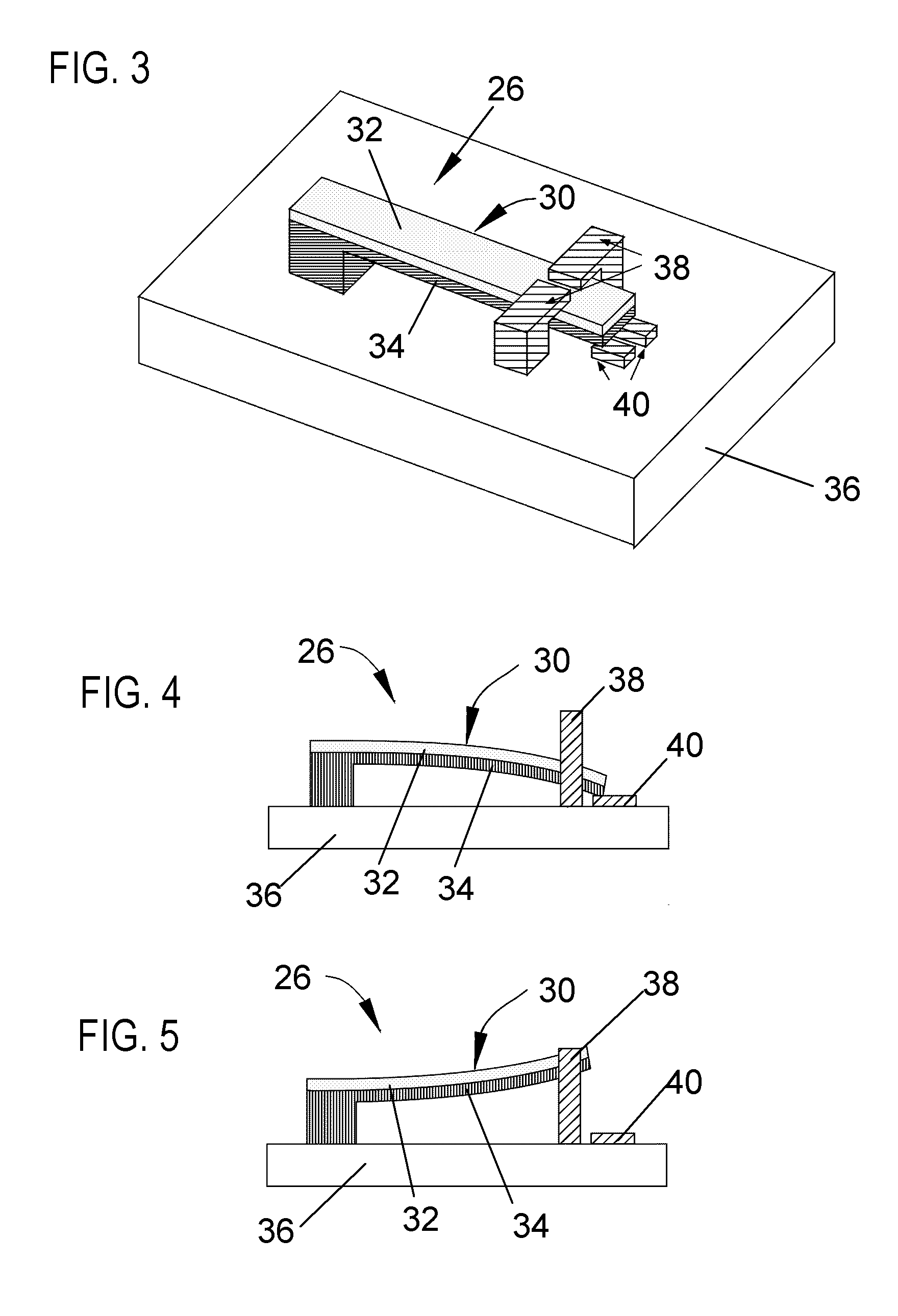
[0029]FIG. 1 schematically represents a microsensor RFID tag 10 in accordance with a preferred embodiment of the invention. FIG. 1 represents components of the tag 10 as including a substrate 12 that carries one or more sensor arrays 14, interface electronics 16, a clock generator (timer crystal) 18, an RFID front-end transceiver 20, an antenna 22, and a battery 24. While the tag 10 of this invention will be discussed with particular reference to humidity and temperature sensing, those skilled in the art will appreciate that technological aspects of the tag 10 can be implemented with other types of sensors, including chemical, shock / vibration, tilt, pressure, acceleration, and biological sensors.

[0030] The substrate 12 can be of any suitable construction and material, such as those currently used in RFID and / or electronics technologies, and therefore will not be discussed in any detail here. Other than as noted below, the clock generator 18, transceiver 20, antenna 22, and battery ...


PUM


Abstract

A sensing system, sensing method, and method of producing a sensing system capable of providing a cumulative measurement capability, such as in the form of a RFID tag capable of measuring cumulative heat and humidity for continuous monitoring of storage and shipping conditions of various goods. The system includes integrated circuitry and a plurality of sensing elements, preferably having cantilevered bimorph beams. Each sensing element is responsive to an environmental condition so as to deflect toward and away from open contacts in response to changes in the environmental condition. Each sensing element produces a digital output when it contacts and closes its open contacts. The integrated circuitry interfaces with the sensing elements so that the digital outputs of the sensing elements are processed to generate a system output of the sensing system.

Description

CROSS REFERENCE TO RELATED APPLICATIONS [0001] This application claims the benefit of U.S. Provisional Application No. 60 / 680,718, filed May 13, 2005, the contents of which are incorporated herein by reference.BACKGROUND OF THE INVENTION [0002] The present invention generally relates to methods and devices capable of monitoring environmental conditions, such as heat and / or humidity, including cumulative monitoring of heat and humidity. More particularly, this invention relates to a sensor in the form of a radio frequency identification (RFID) tag capable of measuring cumulative heat and humidity for continuous monitoring of storage and shipping conditions of items in various applications, including supply-chain management of perishable goods, pharmaceuticals, chemicals, and fresh agriculture products. The sensor RFID tag lends itself to automation and cost-effective supply chain management by using an RFID wireless link for transmission of cumulative sensor data to an RFID-reader (i...

Claims


Application Information

Patent Timeline
IPC IPC(8): H01C7/00
CPCG01K1/024G01K3/04G01K1/045
Inventor YAZDI, NAVID
Owner BELLUTECH LLC
Learn More