Steering wheel equipped with airbag device

a technology of airbags and steering wheels, which is applied in the directions of transportation and packaging, pedestrian/occupant safety arrangements, vehicular safety arrangements, etc., can solve the problems of difficult for drivers to properly conduct the operation of switches, the inability of the visible function of switches to be appropriate, etc., and achieve the effect of improving the visible function of the operational portion

Inactive Publication Date: 2008-10-28
MAZDA MOTOR CORP
View PDF10 Cites 20 Cited by
  • Summary
  • Abstract
  • Description
  • Claims
  • Application Information

AI Technical Summary

Benefits of technology

[0007]The present invention has been devised in view of the above-described problem, and an object of the present invention is to provide a steering wheel equipped with an airbag device in which the airbag cushion is inflated from the pad portion in the doughnut shape, which can improve the visible function of the operational portion, such as a horn switch.

Problems solved by technology

However, since the driver's eyes tend to be turned downward, the visible function of the switches seems not necessarily appropriate.
In particular, it would be difficult for the driver to properly conduct the operation of switches in case of emergency at night.

Method used


Image

  • Steering wheel equipped with airbag device
  • Steering wheel equipped with airbag device
  • Steering wheel equipped with airbag device

Examples


embodiment 1

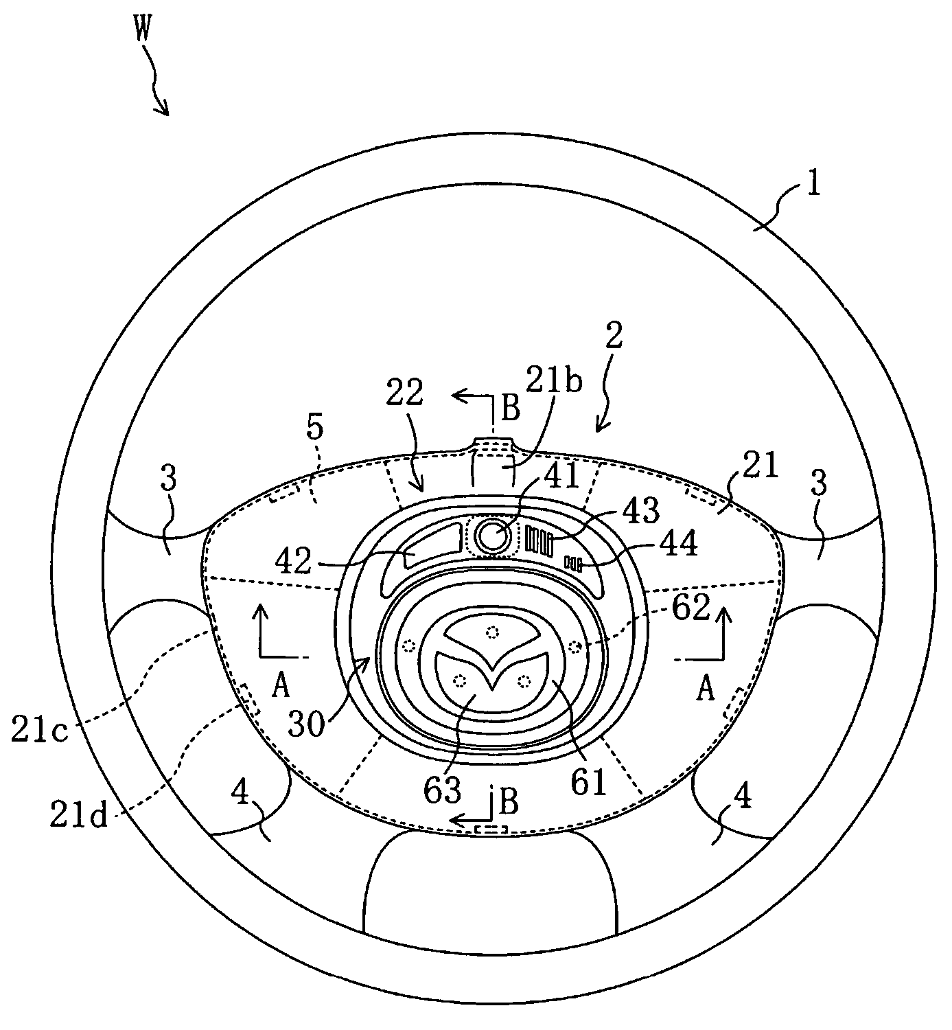
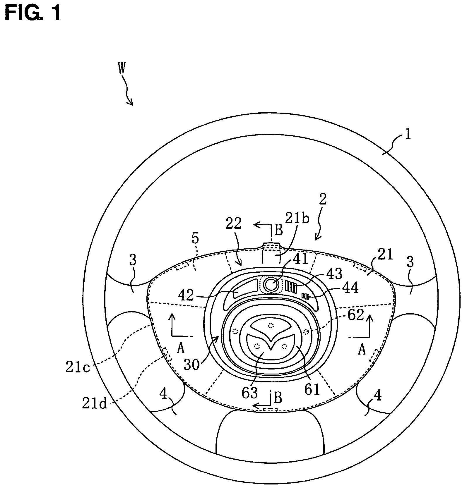
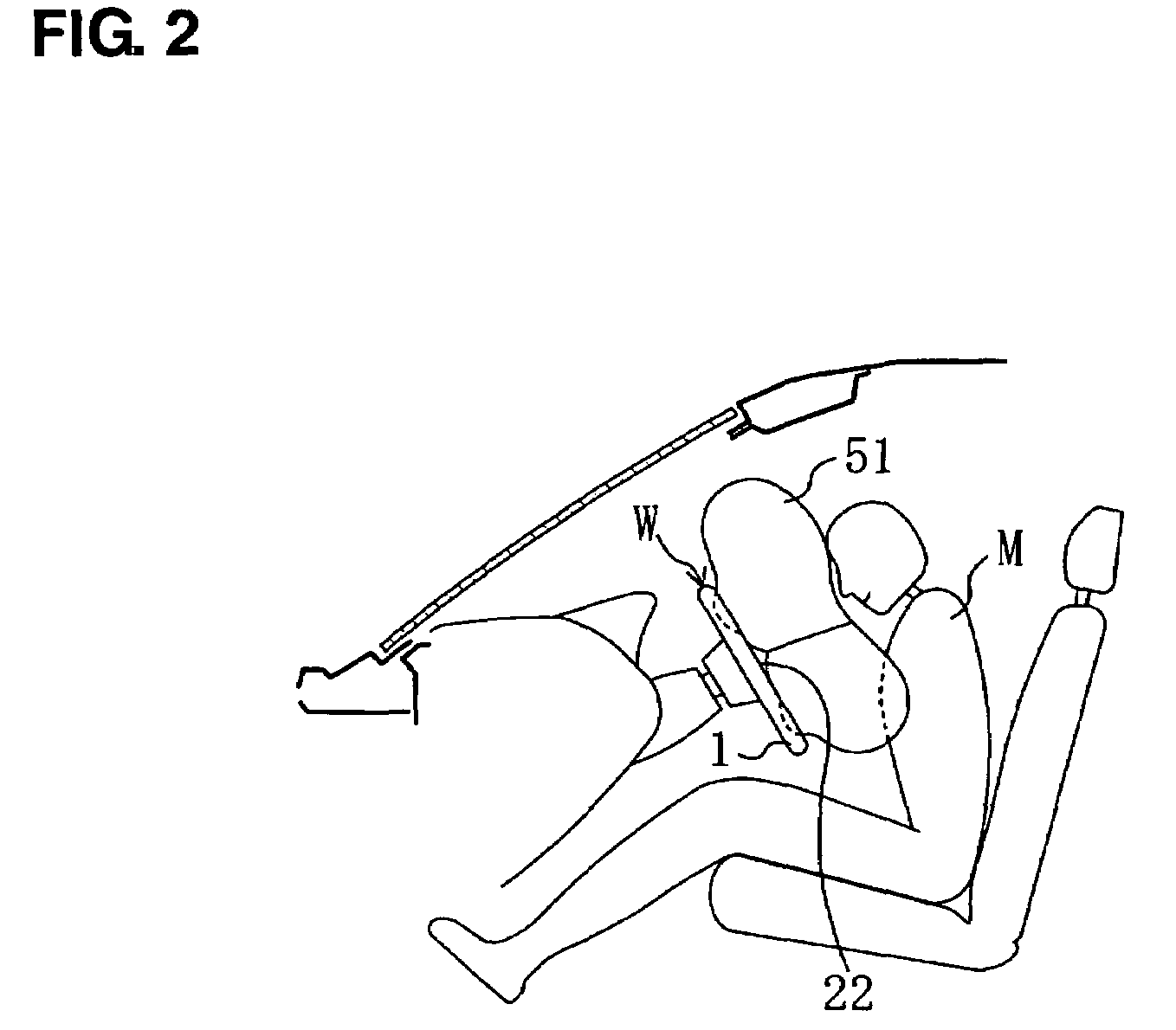
[0034]FIG. 1 illustrates a schematic structure of a steering wheel W equipped with an airbag device according to the first embodiment of the present invention. The steering wheel W comprises a ring portion 1 that is disposed at a peripheral portion and griped by a driver M, a pad portion 2 that is located at the center of the ring portion 1, and four spokes 3, 3, 4, 4 (spoke portions) that interconnect the ring portion 1 and the pad portion 2. An airbag device 5 is disposed in the pad portion 2, and the airbag device 5 inflates an airbag cushion 51 toward the driver M at a vehicle crash as illustrated in FIG. 2. In the present embodiment, the airbag cushion 51 is a doughnut-shape airbag cushion operative to be inflated in a ring shape, which will be described below.

[0035]The spokes 3, 3, 4, 4 are, as illustrated in FIG. 1, comprised of a pair of lateral spokes 3, 3 that extend from upper side ends of the pad portion 2 in the vehicle width direction and a pair of oblique spokes 4, 4 ...

modified embodiment 1

OF THE EMBODIMENT 1

[0060]The above-described illuminator 60 is not limited to the above-described first embodiment in which the light-intercept paint is coated on the driver-side surface of the clear acryl plate 61 and the coated portion is illuminated by the LEDs 62. For example, as illustrated in FIG. 5, a plurality of groove portions (recess portions) 61a, 61a, . . . may be formed on the vehicle-front-side surface of the acryl plate 61, and the groove portions 61a, 61a, . . . may be illuminated by the lights from the side.

[0061]Specifically, on the vehicle-front-side surface of the acryl plate 61 that is provided on the driver side of the switch cover 31 of the horn switch 30 are formed the plural groove portions 61a, 61a, . . . that have substantially a V-shaped section. Thus, plural spaces with V-shaped sections are formed between the acryl plate 61 and the base portion 31b of the switch cover 31.

[0062]Also, dark-color-based paint of black or the like is coated on portions with...

modified embodiment 2

OF THE EMBODIMENT 1

[0067]The above-described illuminator 60 is not limited to the above-described first modified embodiment in which the groove portions 61a, 61a, . . . are formed on the vehicle-front-side surface of the acryl plate 61 and the groove portions 61a, 61a, . . . are illuminated by the LEDs 62 from the side. For example, as illustrated in FIG. 6, two acryl plates 71 and 72 may be provided, spaces with substantially V-shaped section may be formed between them, and the spaces may be illuminated by the lights from vehicle front side.

[0068]Specifically, on the vehicle-front-side surface of the acryl plate 71 (the first clear plate) that is provided on the driver side are formed plural groove portions 71a, 71a, . . . that have substantially the V-shaped section. Also, dark-color-based paint of black or the like is coated on portions without the groove portions 71a, 71a, . . . of the vehicle-front-side surface of the acryl plate 71, so that the mask portion 63 is formed. Meanw...


PUM


Abstract

The illuminator constituting an indirect illumination is provided on the driver side of the switch cover of the horn switch provided at the fixed portion. Specifically, the clear acryl plate is provided on the driver side of the switch cover. On the driver side of the acryl plate is provided the mask portion coated with black paint, while on its vehicle-front-side surface is provided the reflecting portion with coated white paint. The LEDs are provided behind the mask portion and inside the acryl plate. The mask portion constitutes the emblem of vehicle makers, and the emblem portion shines when the LEDs are tuned on. Thus, the visible function of the operational portion (switch cover), which is provided at the fixed portion can be improved.

Description

BACKGROUND OF THE INVENTION[0001]The present invention relates to a steering wheel equipped with an airbag device operative to protect a vehicle driver at a vehicle crash. In particular, the present invention belongs to technology of a specific structure in which an operational portion to operate a vehicle on-board device or the like is provided at a pad portion of the steering wheel.[0002]Conventionally, it is known that the airbag device is provided at the steering wheel to properly reduce an impact that the driver receives at the vehicle crash. Herein, the airbag device is provided in the pad portion of the steering wheel and it inflates an airbag cushion toward the driver when the crash is detected.[0003]It is also known that at the pad portion of the steering wheel equipped with the airbag device are provided an operational portion to operate a vehicle on-board device, such as a horn switch, and / or an indicator of a liquid crystal panel, and that the airbag cushion is disposed ...

Claims


Application Information

Patent Timeline
Patent Type & Authority Patents(United States)
IPC IPC(8): B60R21/16B60R21/20B60R21/203B62D1/04
CPCB60Q3/024B60Q3/044B60Q5/003B60R13/005B60R21/203B60R21/21658B60Q3/14B60Q3/283
Inventor NAKAMURA, KENGONISHIKAJI, SATOSHI
Owner MAZDA MOTOR CORP
Why Eureka
Try Eureka