Planar light source device

a light source device and planar technology, applied in the direction of lighting and heating apparatus, mechanical equipment, instruments, etc., can solve the problems of increasing the number of necessary parts, reducing reliability, and large frame or thickness of the planar light source device, so as to reduce uneven luminance and efficiently disperse heat

Active Publication Date: 2008-10-28
TRIVALE TECH
View PDF6 Cites 55 Cited by
  • Summary
  • Abstract
  • Description
  • Claims
  • Application Information

AI Technical Summary

Benefits of technology

[0009]The present invention has been made in view of the above circumstances and provides a planar light source device using point light sources. According to an aspect of the invention, the planar light source device having a reliable excellent heat dissipating structure and capable of reducing the unevenness in luminance between the proximity to a point light source and the proximity to the area between point light sources adjacent each other.
[0011]According to the above configuration, it may be possible to provide a planar light source device capable of efficiently dissipating heat from a point light source without causing dislocation of a point light source and the dot pattern of a light guide plate and reducing unevenness in luminance between the proximity to a point light source and the proximity to the area between adjacent point light sources.

Problems solved by technology

The planar light source device described in JP-A-2002-229022 or JP-A-2003-76287 is accompanied by a problem that the frame or thickness of the planar light source device becomes large due to its structure or the number of necessary parts is increased.
Further, the reliability is reduced because a viscous material fixing a light source substrate to a bottom case is gradually peeled off with time, or point light sources are dislocated from the dot pattern of a light guide plate from desired positions thus resulting in uneven luminance.
The difference in luminance results in degradation of display quality in a display device using such a planar light source device.

Method used


Image

  • Planar light source device
  • Planar light source device
  • Planar light source device

Examples


embodiment 1

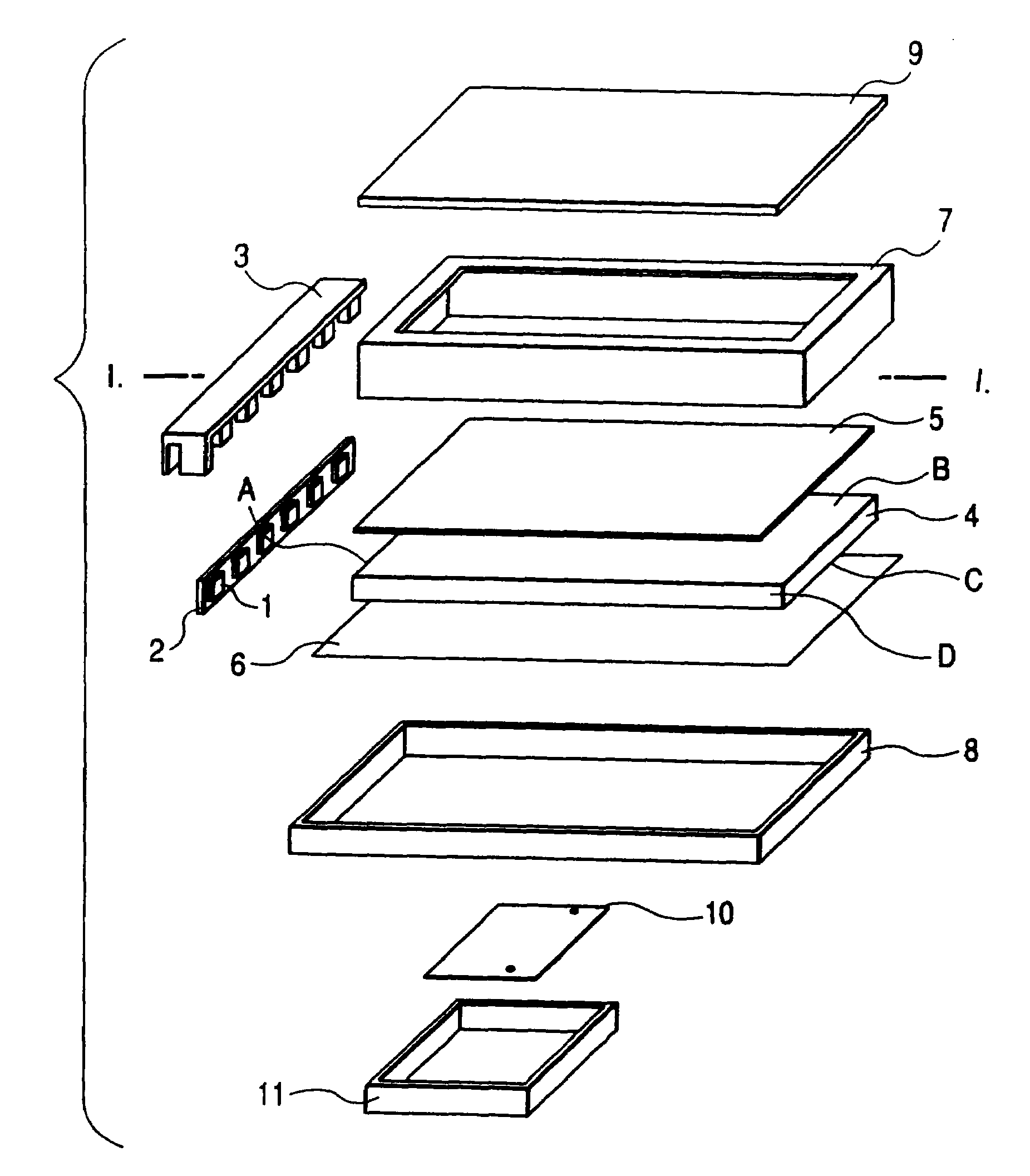
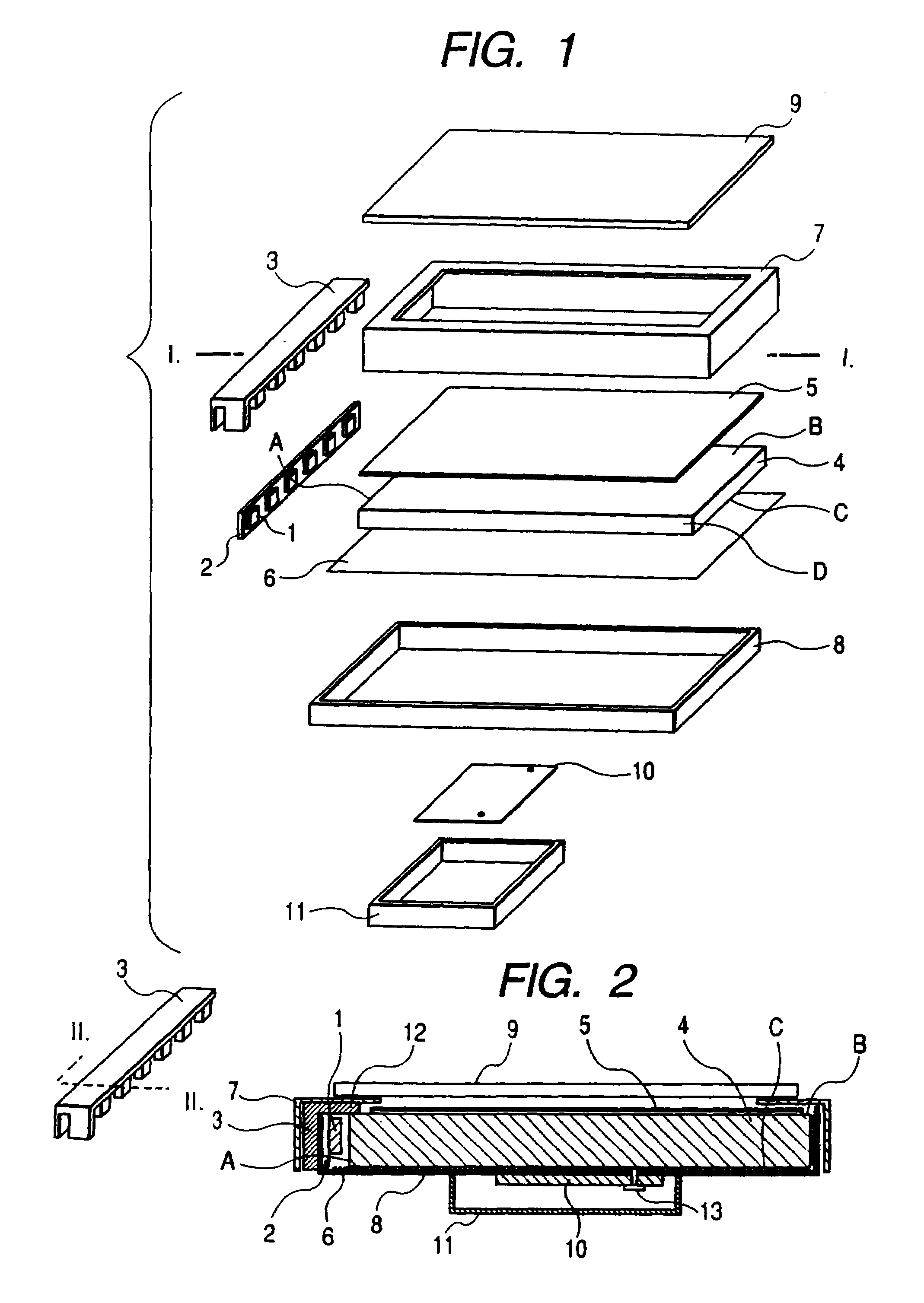
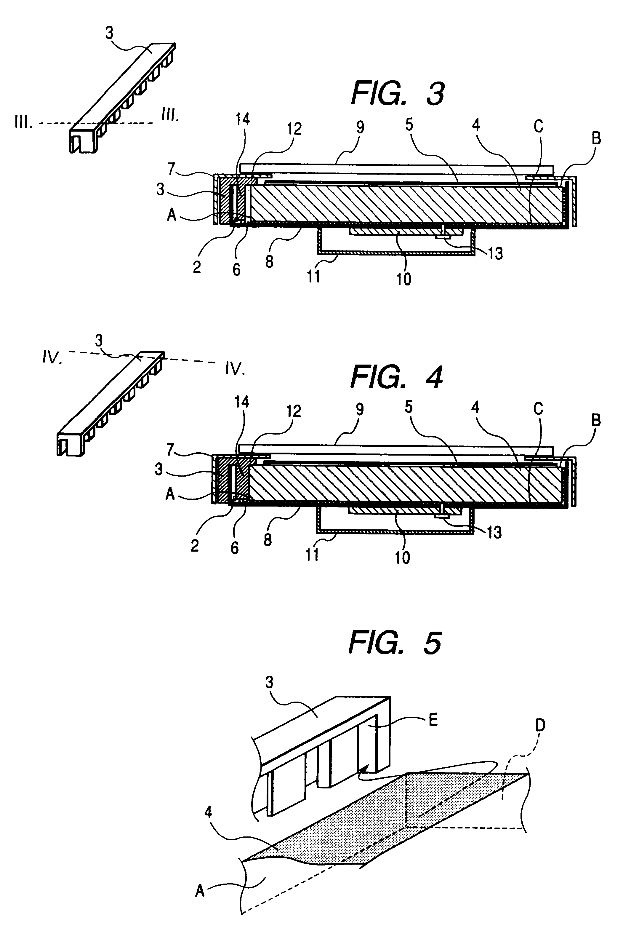
[0021]Embodiment 1 of the invention will be described referring to FIGS. 1 to 5. FIG. 1 is an exploded perspective view illustrating a planar light source device according to Embodiment 1. FIGS. 2 to 4 are cross-sectional views of a display device along the X-X direction assembled and completed from parts shown in the exploded view of FIG. 1. FIG. 5 is an enlarged perspective view of the display device.

[0022]Referring to FIG. 1, a plurality of point light sources 1 such as LEDs are arranged almost in a row while being installed on a light source substrate 2. The light source substrate 2 is supported by a resin frame 3 (the supporting method will be described later). The point light sources 1 are arranged in close proximity to one side of a light guide plate 4. A side A to which light from a light source is incident is hereinafter referred to as a light incident surface. Light from point light sources that enter the light incident surface A is emitted from the light outgoing surface ...

embodiment 2

[0040]Embodiment 2 of the invention will be described referring to FIG. 6. FIG. 6 is cross-sectional view of a display device along the VI-VI direction assembled and completed from parts shown in the exploded view of FIG. 1 according to Embodiment 1. In FIG. 6, same components as those in FIGS. 1 to 5 are given the same reference numbers.

[0041]FIG. 6 shows a planar light source device according to Embodiment 2. Differences from Embodiment 1 will be described. FIG. 6 is a cross-sectional view of the area between adjacent point light sources of the planar light source device according to Embodiment 2. The cross sectional configuration of a point light source and the proximity to both ends of a resin frame of the planar light source device shown in FIG. 6 is the same as that in Embodiment 1. In FIG. 6, Embodiment 2 is different from Embodiment 1 in that a projection 12 of the resin frame 3 coming into contact with the light outgoing surface B of the light guide plate 4 between point li...

embodiment 3

[0044]Embodiment 3 of the invention will be described referring to FIGS. 7 and 8. FIG. 7 shows cross-sectional view of a display device along the VI-VI direction assembled and completed from parts shown in the exploded view of FIG. 1 according to Embodiment 1. FIG. 8 shows an enlarged view of the leftmost side of FIG. 7. In FIGS. 7 and 8, same components as those in FIGS. 1 to 6 are given the same reference numbers.

[0045]FIG. 7 illustrates a planar light source device according to Embodiment 3. Differences from Embodiments 1 and 2 will be described. FIG. 7 is a cross-sectional view of the portion between adjacent point light sources of the planar light source device according to Embodiment 3. The cross sectional configuration of a point light source and the proximity to both ends of a resin frame of the planar light source device shown in FIGS. 7 and 8 is the same as that in Embodiment 1. In FIGS. 7 and 8, Embodiment 3 is different from Embodiments 1 and 2 in that a dome-shaped part...


PUM


Abstract

A planar light source device includes: a plurality of point light sources, each of which emits a light; a light guide plate that includes a first surface, and a second surface perpendicular to the first surface, and that is configured to guide the emitted lights incident from the first surface to be emitted from the second surface; a bottom case including a side portion substantially parallel to the first surface; a light source substrate that includes the plurality of point light sources arranged thereon at a predetermined interval, and that is arranged at a side of the first surface; a frame that sandwiches the light source substrate and the side portion of the bottom case and holds the second surface and that includes a plurality of gaps at positions facing the point light source.

Description

CROSS-REFERENCE TO RELATED APPLICATIONS[0001]This application is based upon and claims the benefit of priority from Japanese Patent Application No. 2006-009711, filed Jan. 18, 2006, the entire contents of which are incorporated herein by reference.BACKGROUND OF THE INVENTION[0002]1. Field of the Invention[0003]The present invention relates to a planar light source device using point light sources and in particular to a planar light source device applicable to a display device using a liquid crystal.[0004]2. Description of the Related Art[0005]A liquid crystal display device, a signboard or a guide lamp is a non-luminous display device rather than a luminous display device including a luminous display part. Such a non-luminous display device requires a planar light source device such as a backlight on the rear surface of a display part. Planar light source devices come in side light type (edge light type) or direct backlight type. The side light type planar light source device has a ...

Claims


Application Information

Patent Timeline
Patent Type & Authority Patents(United States)
IPC IPC(8): F21V7/04F21S2/00F21V8/00F21Y101/02
CPCG02B6/0068G02B6/009G02B6/0043G02F1/133308G02F1/133615G02F1/133322G02F1/133317G02F1/133314G02F1/133628
Inventor SAKAI, SEIJISAKAMOTO, TAKUYA
Owner TRIVALE TECH
Why Eureka
Try Eureka