
Eccentric mounting and adjustment system for belt driven devices

a technology of mounting and adjustment system and belt drive, which is applied in the direction of mechanical control device, gearing, instruments, etc., can solve the problems of increasing maintenance frequency and cost, affecting the operation of the system, so as to reduce the operation of failure, and ensure the effect of stability

Inactive Publication Date: 2008-10-28
SEC OF THE ARMY US GOVERNMENT AS REPRESENTED BY THE
View PDF3 Cites 2 Cited by
  • Summary
  • Abstract
  • Description
  • Claims
  • Application Information

AI Technical Summary

Benefits of technology

[0002]The present invention relates to an eccentric mounting and adjustment (EMA) system for belt driving or belt driven devices that are installed and operated within the restricted confines of an engine compartment, typically a motor vehicle. It satisfies two essential requirements for automotive devices driven by an endless flexible belt. These are: 1) a reliable mounting to the engine block assembly, and 2) a continuous provision of a proper amount of tension to the belt for either driving or driven devices. As a result, there is minimal wear and tear on device bearings and the belt, which reduces operational failures and assures maximum efficiency for these devices.
[0005]My invention allows any flexible belt of the armed forces' inventory to be readily removable, installable, and adjustable by a single person using the simplest of tools, such as a large screwdriver, a pair of pliers, or an elongated rod of about ½ inch in diameter. Thereby, I have avoided former frustrations and expenses involving special tools or fasteners, which can be lost or misplaced. Moreover, minimal force and exertion are expended.
[0007]It is to be understood that the readiness requirements for military vehicles are unusual, and thereby necessitate more reliable and rugged designs than their commercial counterparts. The components must have a good tolerance for more frequent shocks, vibrations, and thermal events because they frequently go from prolonged periods at standing idle to wide open cross-country travel. Further, present art approaches have the potential for reducing readiness, increasing maintenance frequency and costs, as well as exposing personnel to undue risks to reattach or tension belts while engaged in awkward positions or extreme reaches.
[0009]It is therefore an object of this invention to provide an EMA system that properly tensions an endless drive belt. It is a separate object to provide such a system that requires less manual force and effort while installing, tensioning, and operating. It is another object to provide a functional EMA system that is mechanically durable, economical to produce, reliable in construction, simple to manufacture, and capable of achieving a long or trouble free service life.

Problems solved by technology

Such accidents could potentially disrupt or disable hydraulic, electrical, and mechanical systems located therein.
Further, present art approaches have the potential for reducing readiness, increasing maintenance frequency and costs, as well as exposing personnel to undue risks to reattach or tension belts while engaged in awkward positions or extreme reaches.
With use, the belts can become loose and full torque is not easily transmitted to the driven devices.
Thereafter, the belts can slip and become more damaged.
If the belts are too tight, excessive wear can result in the bearing assemblies of the driving or driven devices as well as causing belt shredding or separation.
This impacts operating efficiency.

Method used


Image

  • Eccentric mounting and adjustment system for belt driven devices
  • Eccentric mounting and adjustment system for belt driven devices
  • Eccentric mounting and adjustment system for belt driven devices

Examples


Embodiment Construction

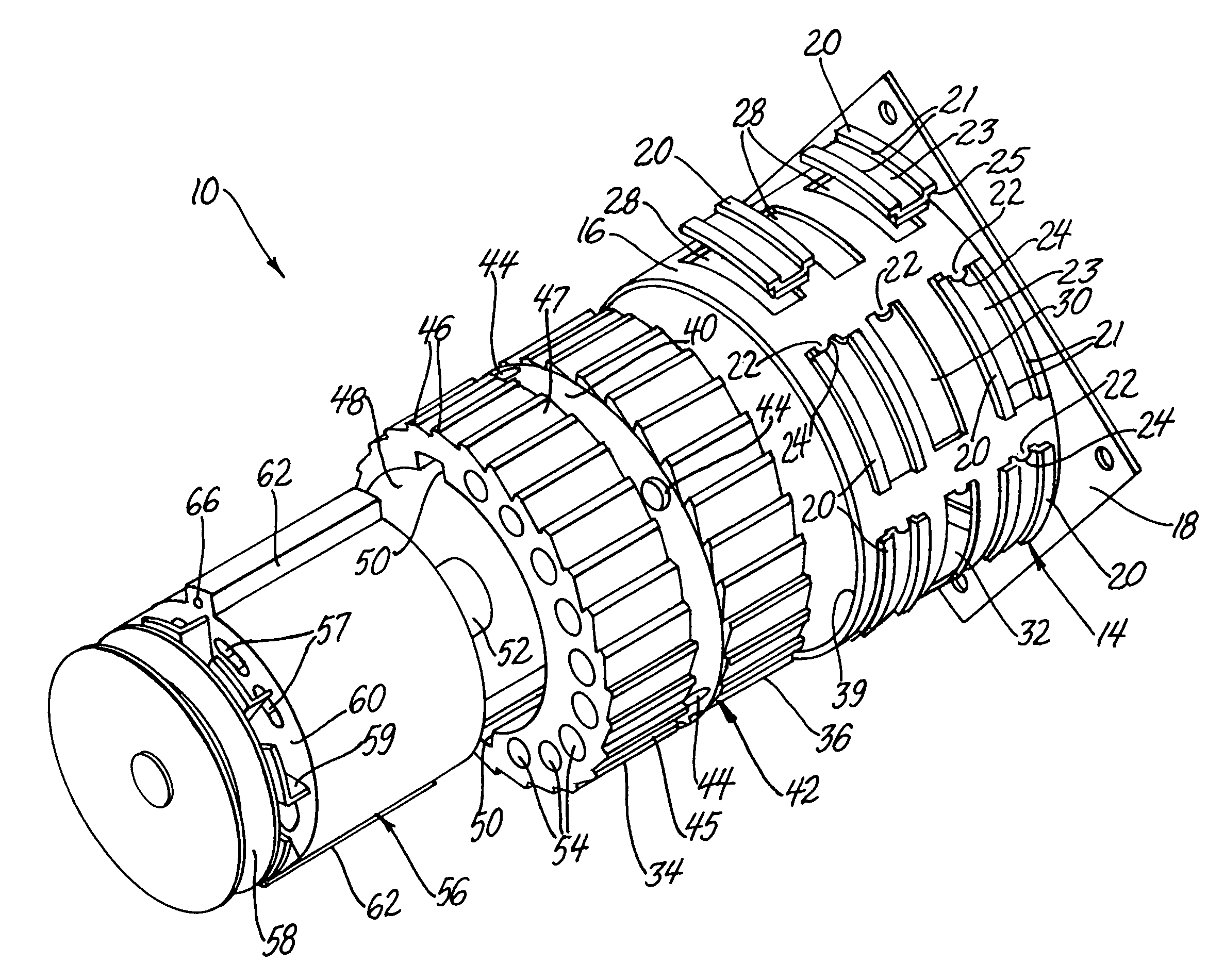
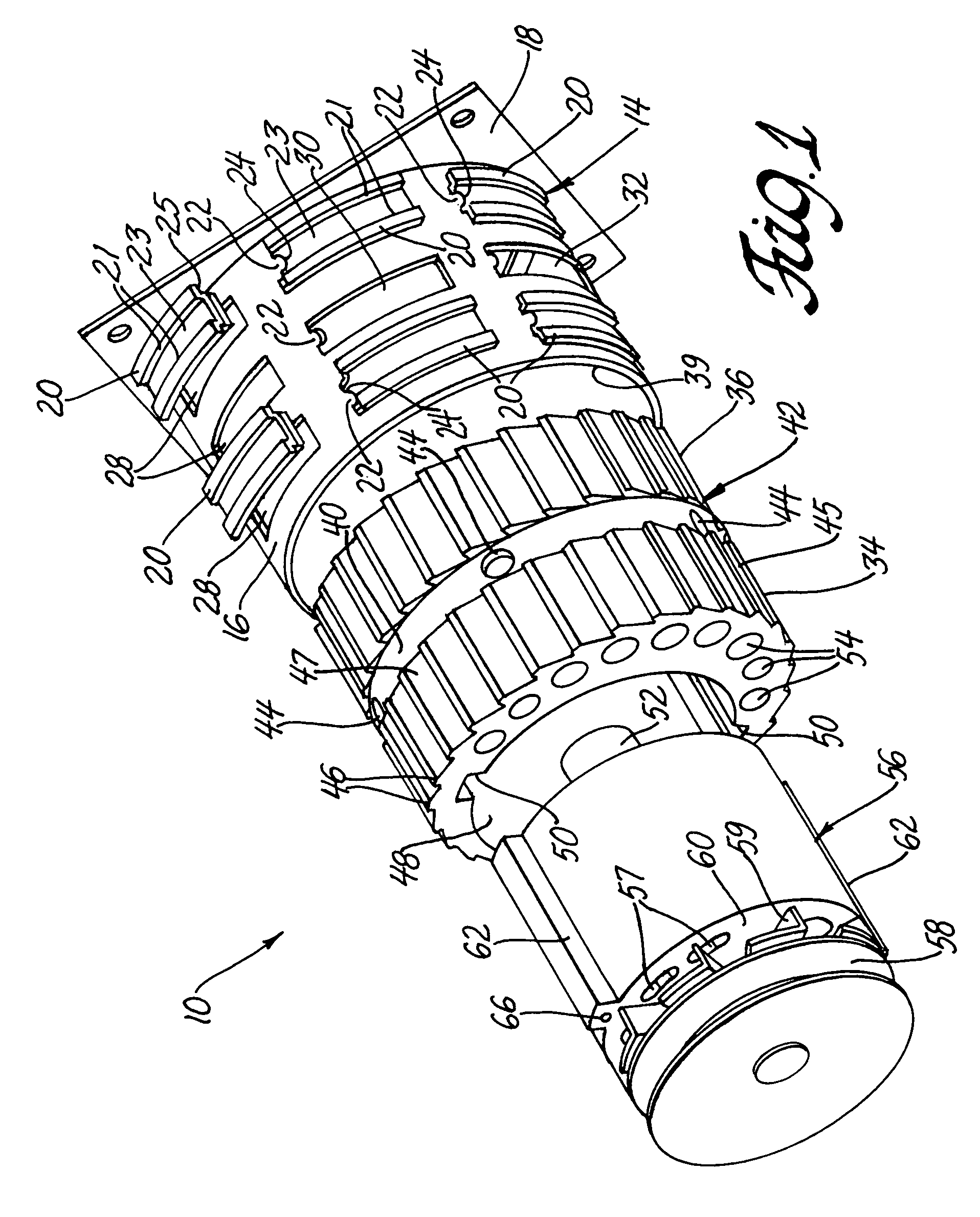
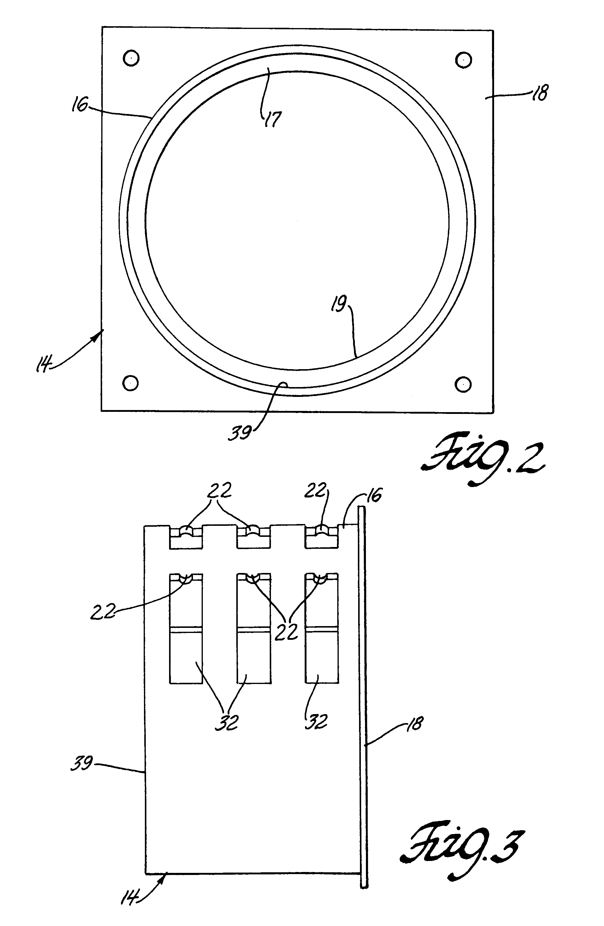
[0017]FIG. 1 depicts an eccentric mounting and assembly system 10. FIG. 4 shows a typical mounting of system 10 to a plate 70 on the engine block 68, wherein the assembly is affixed to plate 70 by bolts passing through the system's rectangular base 18. Plate 70 can be spaced from the engine block to allow clearance for electrical or fluid conduits passing from driven a device 56 through base 18. An endless drive belt 74 rotates driven device 56 in conventional fashion. Besides device 56, system 10 includes an eccentric socket 42 and a housing member 14.

[0018]Returning to FIG. 1, device 56 fits within receiving aperture 48 of socket 42, which preferably is fashioned of a high-strength, heat resistant, non-metallic material. Device 56 is non-rotatably seated in socket 42 by the shape of the socket, or by alternate means, such as axial fixation within the socket by the use of wedges, lugs, flats, or pins. For instance, at least one lug 62 that extends outwardly from the circular surfac...


PUM


Abstract

An eccentric adjustment and mounting system is useful for belt engaging engine components such as alternators or water pumps. The system includes a housing fixed to the engine, a socket rotatable in pawl-and-ratchet fashion within the housing, and a socket aperture eccentrically disposed relative to the socket's axis. The aperture receives the belt engaging component, whereby rotation of the socket moves the component to adjust belt tension.

Description

GOVERNMENT INTEREST[0001]The invention described herein may be made, used, and licensed by, or for, the United States Government for governmental purposes without paying me any royalty.BACKGROUND AND SUMMARY[0002]The present invention relates to an eccentric mounting and adjustment (EMA) system for belt driving or belt driven devices that are installed and operated within the restricted confines of an engine compartment, typically a motor vehicle. It satisfies two essential requirements for automotive devices driven by an endless flexible belt. These are: 1) a reliable mounting to the engine block assembly, and 2) a continuous provision of a proper amount of tension to the belt for either driving or driven devices. As a result, there is minimal wear and tear on device bearings and the belt, which reduces operational failures and assures maximum efficiency for these devices.[0003]The term “belt driven device” includes those devices within motor vehicles that are serviced by endless b...

Claims


Application Information

Patent Timeline
Patent Type & Authority Patents(United States)
IPC IPC(8): F16H7/08F16H7/22
CPCF16H7/14F16H2007/0853Y10T74/20636Y10T74/2133F16H2007/088
Inventor HANSEN, DAVID N.
Owner SEC OF THE ARMY US GOVERNMENT AS REPRESENTED BY THE
Learn More