

Method and device for triggering an electric motor
- Summary
- Abstract
- Description
- Claims
- Application Information
AI Technical Summary
Benefits of technology
Problems solved by technology
Method used
Image

Examples
Embodiment Construction
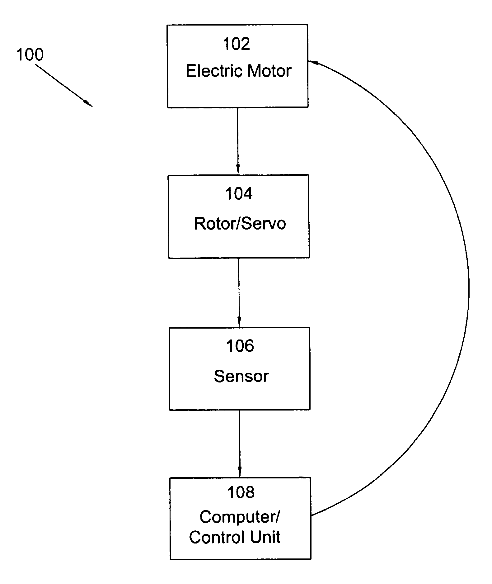
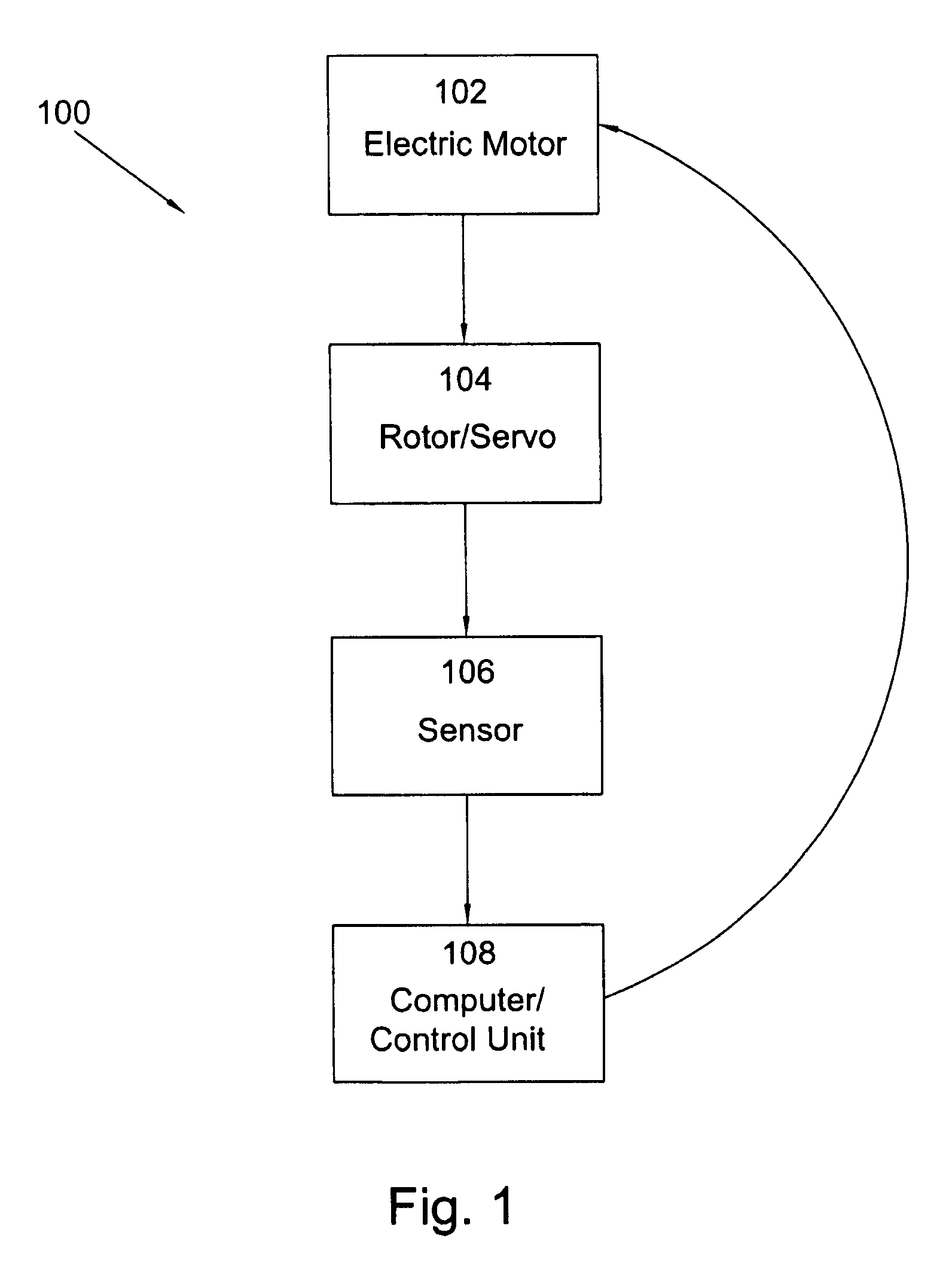
[0014]FIG. 1 is a block diagram of present invention system 100 for triggering an electric motor. System 100 includes electric motor 102 having a rotor 104. In a preferred embodiment, motor102 is an electronically commutated motor. Sensors 106 are used to monitor the operation of rotor 104, for example, to detect the direction of rotation of the rotor and the position of the rotor and to send sensor signals including data regarding the direction and position of the rotor to computer / control unit 108. In a preferred embodiment (not shown), sensors 106 are three Hall sensors staggered with respect to each other by 1200 in the direction of rotation of the rotor. In general, motor 102 operates for a plurality of rotations of the rotor. Unit 108 receives sensor signals for a specified rotation of the rotor, and in some embodiments, also receives directional and positional data for a subsequent rotation of the rotor. In some embodiments, unit 108 stores a predetermined pattern of directio...
PUM
 Abstract
Description
Claims
Application Information